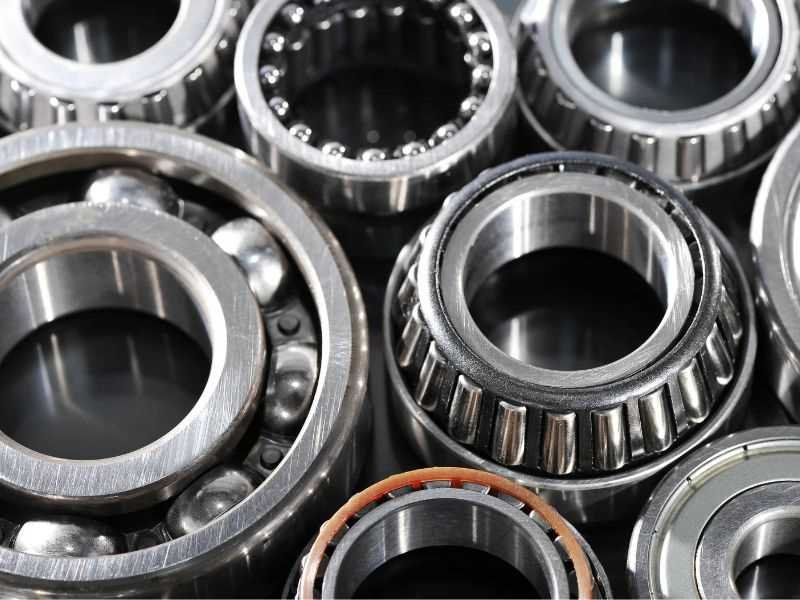
A radial load pushes across the shaft, at right angles to the bearing axis. An axial load, also called a thrust load, pushes along the axis. A combined load has both. The direction is the first thing to settle, because it narrows the bearing types that can carry the load.
| Load | Direction | Typical source | Bearing that suits it |
|---|---|---|---|
| Radial | At right angles to the shaft axis | Weight of a shaft, belt or chain pull, the separating force of a gear | Radial bearings, such as deep groove ball bearings and cylindrical roller bearings |
| Axial (thrust) | Along the shaft axis | Weight of a vertical rotor and impeller, propeller thrust, the axial force of a helical gear | Thrust ball or thrust roller bearings |
| Combined | Both at once | The output shaft of a helical gearbox | Angular contact bearings and other types made for both |
Radial Load: Across the Shaft
A radial load acts at right angles to the shaft axis. The weight of a shaft trying to bend downward is a radial load on the bearings that hold it. So is the pull of a belt on a pulley shaft, because the belt pulls sideways on the shaft.
Catalogue ratings for radial bearings are based on radial load, because most applications are mainly radial. Thrust bearings are rated for axial load.
Axial Load: Along the Shaft
An axial load acts parallel to the shaft axis and tries to push the shaft along its length. A vertical pump shows it well: the weight of the motor rotor and the impeller presses down along the shaft, and a thrust bearing holds it up. A ship propeller is the classic case, where the thrust of the propeller passes through a thrust bearing to the hull.
Gears add axial load in some cases. A table of gear loads gives a tangential force, a radial separating force and an axial force for each gear type. A spur gear and a double-helical gear produce no axial force in theory, while a helical gear does.
Axial load is often confused with movement. Swinging is not by itself an axial load. Thrust appears when force is applied along the axis, for example when a robot arm is pushed into its shoulder joint.
Combined Load and the Fa/Fr Ratio
Many shafts carry both loads at once. Catalogues compare the axial load Fa with the radial load Fr. For rolling bearings the catalogue gives a limit value e, and the axial load enters the calculation only above it. One method for spherical plain bearings, covered below, adds the axial part at every ratio. If the axial load dominates, a thrust bearing is the usual answer.
Which Bearing Takes Which Load
The table lists how common bearing types are used, as described in a general bearing guide.
| Bearing | What it is used for |
|---|---|
| Deep groove ball bearing | Radial and axial loads together, at high speed with low friction |
| Angular contact ball bearing | Radial and axial load together. A single row takes axial load in one direction only, and the axial capacity rises with the contact angle |
| Thrust ball bearing | Axial loads. A double-direction type is not suitable for radial loads |
| Cylindrical roller bearing | High speed and heavy radial load |
| Spherical roller bearing | Heavy radial and axial loads |
| Tapered roller bearing | Heavy radial and axial loads |
| Thrust roller bearing | A standard type takes heavier axial loads than a thrust ball bearing and should not see radial loads. Tapered thrust roller bearings and thrust spherical bearings take both |
How to Find the Radial Load on a Bearing
A load seldom comes from a simple calculation, because it is not always constant. It comes from the weight of what the bearing supports, from belt, chain or gear transmission, and from forces that appear in operation. Bearing makers therefore multiply the theoretical value by empirical coefficients.
One maker's guide uses a load coefficient fw, which covers vibration and impact. Other catalogues use their own factors.
| Operating condition | Examples | fw |
|---|---|---|
| Little vibration or impact | Motors, machine tools, measuring instruments | 1.0 to 1.2 |
| Normal operation with slight impact | Automobiles, air blowers, compressors, agricultural equipment | 1.2 to 2.0 |
| Severe vibration or impact | Crushers, construction equipment, shaker screens | 2.0 to 3.0 |
In the same guide, a belt drive starts from the effective transmission force of the belt. That force is multiplied by fw and by a belt coefficient fb, which covers belt tension.
| Drive | fb |
|---|---|
| Timing belt | 1.3 to 2.0 |
| V-belt | 2.0 to 2.5 |
| Flat belt with tension pulley | 2.5 to 3.0 |
| Flat belt | 4.0 to 5.0 |
| Chain | 1.2 to 1.5 |
As an illustration with assumed numbers, take a motor with a V-belt that transmits an effective force of 500 N. At fw 1.2 and fb 2.0 to 2.5, the load on the pulley shaft is 500 × 1.2 × 2.0 = 1,200 N up to 500 × 1.2 × 2.5 = 1,500 N. Use the belt maker's data for the real coefficient.
A shaft is usually carried by two bearings, and each takes a share that depends on the size and position of the load and on the distance between the bearing centers. Calculate the radial force components first, then add them as vectors in the load direction. Gear loads are handled the same way, with the tangential and separating forces added as vectors. They use fw and a gear coefficient fg, 1.0 to 1.1 for precision gears and 1.1 to 1.3 for normal gears, instead of the belt coefficient.
Equivalent Load: Turning Axial Load Into Radial Load
For radial bearings the ratings are radial, so a combined load is converted into one equivalent radial load. The catalogue gives the factors, usually called X for the radial load and Y for the axial load. If the axial load dominates, a thrust bearing is the usual answer, since the radial rating no longer describes the duty.
Take the method, the ratings and the factors from the same catalogue.
Radial and Axial Load in Rod Ends and Spherical Bearings
A spherical plain bearing carries radial and axial load together, and it is rated mainly for radial load. In a rod end the pin passes through the ball at right angles to the rod, so a push or pull along the rod loads the bearing radially. Load along the pin axis is axial.
The catalogues for GE-type bearings that we could read give no separate axial rating. They give a method instead. One published selection guide adds the axial load, multiplied by a factor Y, to the radial load. It states the method for a load of constant size and direction. Y is 0.8 for an Fa/Fr up to 0.1 and rises to 3 for a ratio up to 0.5, and the guide gives no factor beyond 0.5. When the load is mainly axial, a thrust spherical plain bearing is the usual choice. Angular contact spherical bearings are made for thrust loads beyond what a radial spherical bearing can carry.
The size and load checks for a spherical bearing are covered in how to select a spherical bearing size.
The wider range of types, materials and sizes is in the spherical bearings guide.
Profab Machine makes stainless steel spherical bearings in metric and inch sizes. Send the radial load, the axial load and the motion with your quote request, and we confirm the series and size.
Common Mistakes With Radial and Axial Load
| Mistake | What goes wrong | What to do |
|---|---|---|
| Calling any motion thrust | A swinging arm puts little thrust on its joint, so the bearing is chosen for the wrong load | Treat only force along the axis as axial load |
| Using the calculated load as it is | Vibration and impact make the real load greater than the calculation | Apply the load coefficient fw, and fb for belts or fg for gears |
| Ignoring the axial force of a helical gear | The bearing sees thrust that was never in the calculation | Check the gear type and add its axial force |
| Mixing factors and ratings from different catalogues | The factors are set for the ratings of their own catalogue, so the result may not hold | Take the method, ratings and factors from one catalogue |
| Using a radial bearing for a mainly axial load | The radial rating does not describe the duty | Choose a thrust bearing when the axial load dominates |
Conclusion
Radial load acts across the shaft and axial load acts along it. Find which one you have first, because the direction and the share of axial load narrow the bearing type. Then work out the load on the bearing, using the coefficients for belt or gear drives where they apply. Convert any axial part into an equivalent radial load to size a radial bearing. For a spherical bearing the same steps apply, with the limits of the published factors in mind.