- By Profab /
- April 29, 2026
Table of Contents
When a spherical bearing fails long before it should, most people look first at load rating or lubrication. That makes sense. Either one can shorten service life fast. But there is another failure cause that is often already built into the assembly before the bearing ever sees its first load cycle: the bearing was installed beyond its allowable misalignment angle, and nobody verified it.
Misalignment is one of the main reasons spherical bearings are used in the first place. It is also one of the easiest limits to overlook.
What Misalignment Means in a Spherical Bearing
A spherical plain bearing handles angular misalignment by letting the ball pivot inside the outer race. A standard radial bearing needs the shaft and housing to stay closely aligned. A spherical plain bearing is different. It can accept an angular offset between the shaft and the housing bore without pushing unwanted bending moments into the surrounding structure.
In catalogs, the misalignment angle is usually shown as alpha. It is the maximum angle between the ball bore centerline and the outer ring centerline when the bearing reaches its extreme displaced position. Since the ball can pivot the same amount in either direction from center, the total available angular movement is 2 x alpha.
That self-aligning geometry is what makes spherical plain bearings useful in linkages, articulating joints, hydraulic actuators, and mounting points where assembly tolerance or working movement creates an angle between the shaft and the housing. The bearing takes up that geometry so the rest of the structure does not have to.
Standard vs High-Misalignment Series: Know Your Limit Before You Size
Not every spherical plain bearing allows the same misalignment angle. Standard series bearings, conforming to ISO 12240-1, typically allow misalignment angles in the range of 3° to 12°, depending on size and design series. High-misalignment series bearings use an extended inner ring width so the ball can pivot farther before contacting the housing face. These designs extend the range to 15°–20°, and in some custom configurations even higher.
The catalog misalignment angle is not a rough suggestion. It is the geometric limit where the ball can still rotate without its edge contacting the chamfer or face of the outer race. Once that angle is exceeded, contact moves away from the intended bearing surface and onto the edge of the inner ring. That is edge loading.
What Edge Loading Does to a Bearing
Edge loading forces the full contact stress into a small area near the ring edge instead of spreading it across the designed contact zone. The contact pressure at that edge can be many times higher than the nominal bearing stress calculated from the load rating. Wear then accelerates quickly. PTFE or composite liners can be damaged in a short time, while metal-to-metal bearings may develop fretting and surface fatigue.
The important thing about edge loading is that it tends to feed on itself. Once edge wear starts, the ball’s contact geometry changes. That can increase the effective misalignment angle and speed up the damage. A bearing may look perfect at installation and still begin degrading from the first load cycle.
Sealed bearings add another detail that is easy to miss. Integral seals can reduce the practical misalignment angle below the bearing’s geometric maximum. As the ball pivots to a high angle, the seal on one side may lose contact and allow contamination in. The opposite side may compress and distort. In sealed bearings, the usable misalignment limit is often governed by the seal’s angular range, not by the metal geometry. Catalogs usually list this separately, and it is often several degrees lower than the geometric limit.
What exceeding the misalignment limit actually does:
- Shifts contact from designed bearing surface to inner ring edge
- Multiplies contact pressure far above nominal load rating values
- Accelerates liner wear in PTFE designs; causes fretting in metal-to-metal designs
- Starts a self-reinforcing failure cycle from the first load application
How Misalignment Interacts with Load Capacity
Spherical plain bearings have two load rating values: the static load rating (C0) and the dynamic load rating (C).
The static load rating applies when a bearing stays stationary under load, makes only occasional alignment movements, or sees heavy shock loads with limited oscillation. The dynamic load rating applies when the bearing has continuous oscillating movement at a defined sliding velocity. In most linkage and actuator applications, both ratings need to be checked.
What gets missed more often is the directional imbalance in load capacity. Spherical plain bearings are mainly designed for radial loads. Their axial load capacity is only a fraction of the radial rating, typically 5–10% of the ultimate radial load. If the load direction changes, or if the shaft angle creates an axial force component through the bearing, the effective radial load capacity can drop significantly.
There is also a stainless steel detail worth checking carefully. 316 stainless bearings carry lower load ratings than equivalent chrome steel bearings of the same size. If a standard steel bearing is replaced with a stainless version for corrosion resistance, the rated load capacity goes down. The bearing should be sized again using the stainless rating, not the chrome steel catalog value.
Misalignment makes this more severe. When a bearing is installed close to its rated maximum angle, the load vector is no longer perpendicular to the bearing face. That introduces an axial component the bearing may not have been sized for. The combined stress state can be worse than either the radial or axial load considered on its own.
The table below summarizes key selection parameters across three common spherical bearing configurations:
| Configuration | Misalignment Range | Load Type Strength | Lubrication | Best Application |
|---|---|---|---|---|
| Standard metal-to-metal | ±3°–±8° | High radial, low axial | Required (grease/oil) | High-load oscillating linkages |
| PTFE-lined (standard) | ±3°–±12° | Moderate radial | Self-lubricating | Low-maintenance, clean/marine environments |
| High-misalignment PTFE | ±10°–±20° | Moderate radial, reduced axial | Self-lubricating | Large angular movement, actuator mounts |
PTFE-Lined vs Metal-to-Metal: Misalignment Tolerance Differs
The liner material affects more than friction and maintenance. It also changes how the bearing reacts when alignment is not ideal.
PTFE-lined bearings transfer a thin layer of PTFE onto the mating ball surface during operation. This creates a self-renewing lubricating film. The PTFE layer has some compliance, so it can tolerate minor geometric imperfections and slight deviations near the rated misalignment angle better than a hard metal-to-metal interface. That is one reason PTFE-lined bearings are common in marine hardware, food processing equipment, and architectural applications where regular maintenance is difficult. The coefficient of friction for PTFE-lined bearings is typically 0.02 to 0.10.
Metal-to-metal bearings rely on hardened steel-on-steel contact with grease or oil as the lubricant. Their contact geometry is less forgiving under edge loading because there is no compliant liner to help distribute stress. The tradeoff is load capacity. Metal-to-metal designs carry significantly higher loads for the same bearing size, and in continuously oscillating applications such as hydraulic actuators, they usually outperform PTFE designs on load life when lubrication is handled correctly.
For stainless steel spherical bearings in corrosive environments, both configurations are available. 316 or 316L stainless provides adequate resistance to chloride-bearing atmospheres and seawater splash. In immersed or highly aggressive conditions, liner choice becomes just as important as the base material. PTFE-lined stainless bearings are often the better choice because they do not need periodic grease replenishment, which may be impractical in submerged or enclosed mounting locations.
Quick guide: PTFE-lined vs metal-to-metal for corrosive service
- Marine splash zone, food-grade, architectural: PTFE-lined stainless (no relubrication needed)
- High-load hydraulic linkage, oscillating actuators: metal-to-metal stainless with sealed grease
- Both types: verify 316/316L grade for saltwater environments, not 304
- Check misalignment angle per configuration: PTFE series typically allows wider range
Five Steps Before You Finalize the Selection
Most spherical bearing sizing errors are not bad calculations. They are missed checks. A bearing can be correctly sized for load and still fail if misalignment is ignored. It can also be correctly sized for misalignment and still fail if the axial load component is left out. The result looks much like an undersized bearing, just slower and often with no obvious warning during commissioning.
A practical selection sequence for any spherical plain bearing application:
Step 1: Measure the actual misalignment angle. Do not estimate it from the drawing. Measure the installed angle at the assembled extremes, including any deflection that occurs under load. Add a margin of at least 20% to the measured angle before comparing it with the catalog.
Step 2: Match the bearing series to the measured angle. If the measured angle plus margin falls outside the standard series range, use a high-misalignment series. Do not undersize the bearing and rely on “careful installation” to make it work.
Step 3: Check the axial load component. If the load direction is not strictly radial, calculate the axial component. Confirm that it falls within the bearing’s rated axial capacity, which is typically 5–10% of the ultimate radial load for standard series.
Step 4: Select liner type based on maintenance access and environment. Use PTFE-lined bearings where maintenance access is limited, corrosion is a concern, or food-contact requirements apply. Use metal-to-metal bearings for high-load oscillating duty where a lubrication schedule can be maintained.
Step 5: Verify housing bore tolerance. An oversized housing bore creates immediate radial preload, increases friction, and can introduce effective misalignment even when the shaft itself is aligned. For precision applications, welded housings often need post-installation reaming.
From aerospace control linkages to marine hydraulic actuators, misalignment angle selection is a critical failure-prevention step that changes by industry, load case, and mounting geometry. The spherical plain bearing family covers many configurations, and correct selection means matching the bearing series to the real geometry, not only to the nominal load.
Choosing the Right Bearing for Your Application
Spherical plain bearings are reliable, compact, and effective when selected correctly. Most avoidable failures happen when the angle check is skipped, or when the installation geometry is assumed to be correct without measurement.
Before finalizing a selection, three questions matter most: What is the maximum misalignment angle in service? What axial load component appears at that angle? And what does the maintenance environment allow for lubrication access?
For high-load applications with moderate misalignment, a metal-to-metal bearing in the correct series is usually the better fit. For corrosive or maintenance-restricted applications with significant angular movement, a PTFE-lined stainless series is often the more practical choice.
Profab Machine supplies custom-specified stainless steel spherical bearings to OEM buyers and engineering teams across marine, industrial, and architectural sectors.
Send Inquiry Now
Related Resource
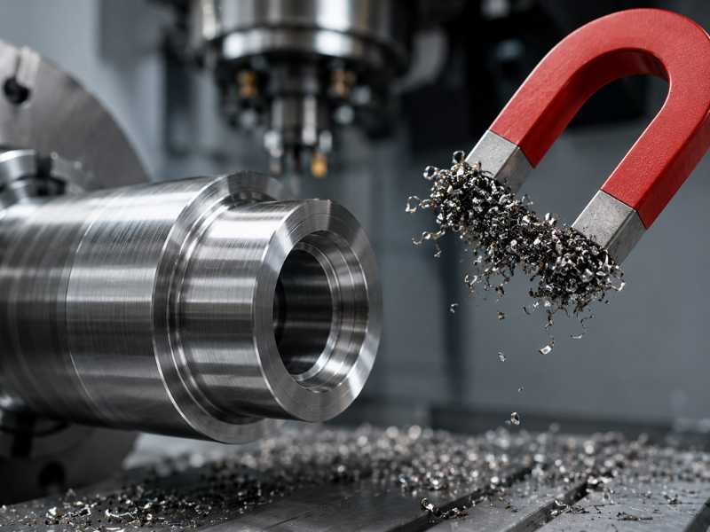
Why Is Stainless Steel Magnetic After Machining?
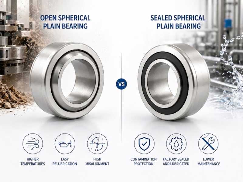
Open vs Sealed Spherical Plain Bearings: How to Choose
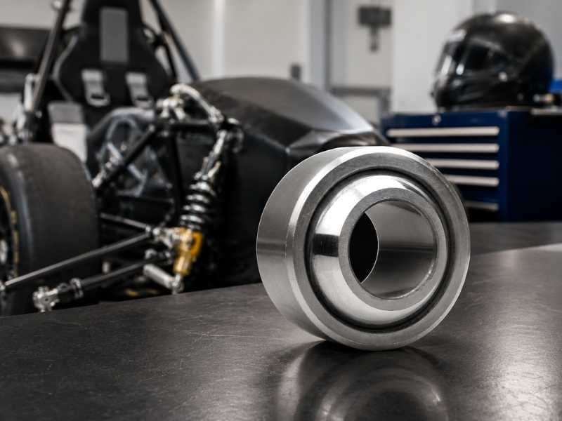
Stainless Steel Spherical Plain Bearings in FSAE and Motorsport Suspension