What Is 5-Axis CNC Machining?
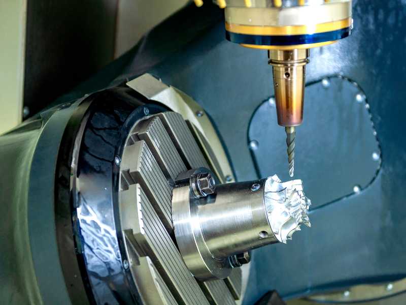
A 5-axis CNC machine moves either the cutting tool or the workpiece along five axes: three linear axes, X, Y, and Z, plus two rotary axes, usually A and B or B and C.
One point gets missed in many beginner explanations. A 5-axis machine does not always move all five axes during the cut. In real shops, 5-axis work usually falls into two different modes.
3+2 (Indexed / Positional) Machining
In 3+2 machining, the rotary axes tilt the part to a fixed angle and then lock in place. After that, standard 3-axis toolpaths do the cutting. The machine can reposition between angles, but the rotary axes do not move during the actual cut.
This works well for parts with features on multiple faces, as long as those features do not require continuous curvature. Valve bodies, brackets, and housings are common examples. Impellers are not.
Continuous (Simultaneous) 5-Axis Machining
In continuous 5-axis machining, all five axes move together throughout the cut. The tool keeps changing its angle relative to the surface as the machine moves.
This is the right approach for turbine blades, impellers, medical implants, and sculpted surfaces. In those parts, the cutting angle has to change continuously if you want a consistent surface finish.
The practical difference matters. Many shops buy a continuous 5-axis machine when 3+2 positioning would have solved most of their work with less programming effort. Learning 3+2 first, before taking on continuous simultaneous programming, is the more common and more forgiving path into 5-axis work.
The Five Axes, Explained
| Axis | Type | Movement | Common Configuration |
|---|---|---|---|
| X | Linear | Left ↔ Right | All machine types |
| Y | Linear | Front ↔ Back | All machine types |
| Z | Linear | Up ↔ Down | All machine types |
| A | Rotary | Rotation around X-axis | Table/Table, Head/Table |
| B | Rotary | Rotation around Y-axis | Table/Table |
| C | Rotary | Rotation around Z-axis | Head/Head, some Table/Table |
Three common machine configurations:
| Configuration | How It Works | Best For |
|---|---|---|
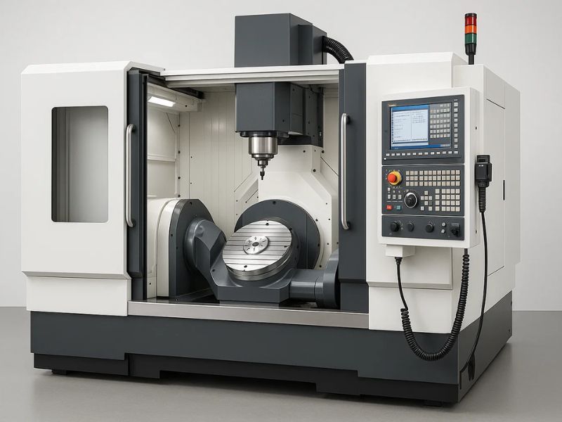
| Table/Table (Trunnion) | Both rotary axes in the table. Part tilts and spins. | Small-to-medium parts, deep cavities, mold-making |
| Head/Head | Both rotary axes in the spindle head. Table stays fixed. | Large, heavy workpieces (aerospace structural parts) |
| Head/Table (Hybrid) | One rotary in the head, one in the table. | General-purpose, balanced flexibility |
When Do You Actually Need 5-Axis?
The question every shop eventually has to answer is simple: can this part be done on 3-axis, or does it need 5-axis? Most shops answer it by looking at setup count, access, tolerance, and finish.
You probably need 5-axis if your part requires three or more setups on a 3-axis machine. At that point, tolerance stack alone can justify the upgrade.
You also need to consider 5-axis when the part has compound angles or undercuts that no single 3-axis orientation can reach. The same applies when contoured faces need a better surface finish and long-reach tool holders are causing deflection.
Prototype tooling is another common case. If setup time dominates the total job cost, 5-axis can pay for itself by reducing handling, alignment, and second-operation errors.
Tight multi-face tolerances matter too. If the customer drawing specifies true position tolerances under 0.001" across features on different faces, repeated 3-axis setups become risky fast.
You can probably stay with 3-axis if all features are orthogonal, meaning the faces are only parallel or perpendicular. Standard fixturing also works well when the part can be finished in one or two setups.
For high-volume production, dedicated multi-part fixtures on a 3-axis machine may still win on cycle time. If your tolerance requirements are ±0.005" or looser, 3-axis may be the more practical route.
The shop-floor reality is less theoretical than most brochures make it sound. A useful rule of thumb: once setup time exceeds roughly 40% of total part time across multiple jobs, the switch to 5-axis typically pays for itself within a year or so, largely through reduced scrap from misaligned second operations.
What Does 5-Axis Really Cost?
This is the question many online articles avoid. Based on current market prices, the numbers usually fall into these ranges.
| Tier | Machine Examples | Price Range | What You Get |
|---|---|---|---|
| Entry | Haas UMC-500, Doosan DVF 5000 | $150K – $250K | Reliable for ±0.001" work. Haas adequate for looser tolerances; Doosan better for consistency. |
| Mid-Range | Methods MB650U, DMG MORI DMU 50 | $250K – $450K | HSK tooling, higher RPM spindles, better thermal stability, tighter accuracy over long runs. |
| High-End | GROB, Hermle, Yasda | $500K – $1M+ | Sub-micron accuracy, lights-out automation-ready, full 5-axis simultaneous at high feed rates. |
| Desktop/Hobbyist | Pocket NC V2-50 | $5K – $15K | Can cut aluminum and mild steel with very light passes. Workspace is tiny (< 50 mm cube for 5-axis work). Not for production. |
Tooling is the first hidden cost. Budget another 15K to 25K for tool holders, cutting tools, workholding, and probing. 5-axis machines need shorter, more specialized holders because collision risk is higher.
CAM software is the second hidden cost. This catches more first-time 5-axis buyers than almost anything else.
Profab Machine coordinates 5-axis CNC machining for stainless steel components, including rod ends, spherical bearings, and custom marine hardware, available on request through our process network for parts whose geometry calls for it.
The CAM Software Problem Nobody Talks About
The barrier to desktop 5-axis isn't building a rigid machine in a hobbyist footprint. It's that 5-axis CAM software is priced astronomically high compared to 3-axis packages, and that cost surprises more first-time buyers than the machine price itself.
| CAM Software | 3-Axis (Annual) | 5-Axis (Annual) | Jump |
|---|---|---|---|
| Mastercam | ~$100/year (student) | $8,000–$15,000/year (commercial) | 80–150× |
| Fusion 360 | $680/year (commercial) | $1,500/year (with machining extension) | 2.2× |
| Siemens NX CAM | N/A | $12,000–$25,000/year | — |
For a small shop, Fusion 360's machining extension is usually the most accessible 5-axis CAM entry point. Mastercam and NX are common in high-end production, but the annual cost can reach five figures. The software alone can equal 10% to 15% of your machine payment, and that cost comes back every year.
A serious 5-axis CAM package needs TCPM or RTCP support. TCPM means Tool Center Point Management. It keeps the tool tip at the programmed position while the rotary axes tilt. Without it, you are doing the trigonometry by hand for every setup.
You also need full machine simulation, not just toolpath simulation. The software has to model the full machine kinematics, including the spindle head, table, and fixture. That is how you catch collisions before the machine does.
The post-processor matters as much as the toolpath. A generic 5-axis post can crash your machine. You need one tuned to your specific kinematics.
Desktop 5-Axis: Is It Real?
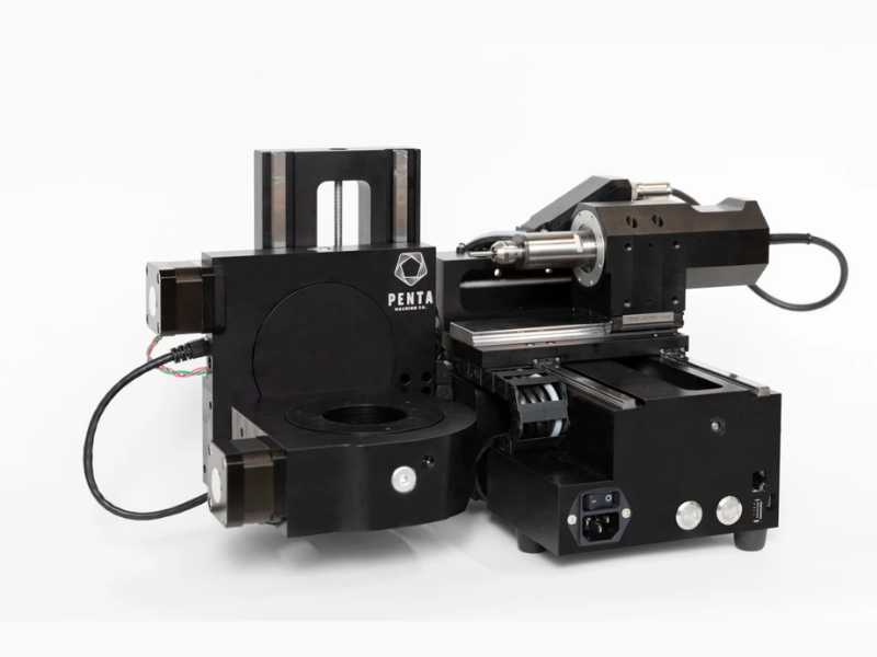
Yes, desktop 5-axis is real. It is just not what many people hope it is. The Pocket NC V2-50, usually around $5,000–$7,000, is the best-known desktop 5-axis machine. It can cut aluminum, brass, and mild steel, but the limits are serious.
The workspace is roughly a 50 mm cube for true 5-axis work. In 3-axis mode, you may get around 100 mm. Material removal rate is very low. Think "engraving," not production machining. Light passes are the rule.
Rigidity is also limited. A real VMC is far stiffer. Chatter becomes part of the daily fight. It is slow and loud for the amount of material it removes. In practice, it can cut a wide range of small parts, but not quickly or quietly, and the window of cutting parameters that actually work well is narrow.
The Pocket NC makes sense for educators teaching 5-axis concepts, hobbyists making very small aluminum parts, and shops evaluating whether 5-axis is worth a larger investment. It is not a production machine. For CAM, Fusion 360's machining extension at about $1,500 per year is the most realistic budget path.
The Process: From CAD to Finished Part
CAD Design. The process starts with a 3D model in SolidWorks, Fusion 360, or similar software. This is where you define the part geometry and the critical tolerances.
CAM Programming. The programmer generates toolpaths in 5-axis CAM software. They define drive surfaces, which are the surfaces to cut. They also define check surfaces, which are the areas the tool must avoid. Tool orientation strategy is part of the same step. The software then outputs G-code through a post-processor built for that machine's kinematics.
Setup and Work Offsets. The workpiece is fixtured, and TCPM is configured. TCPM tells the controller where the tool tip sits relative to the rotary center. A small setup error here can scrap the part. Even a few thousandths of an inch can matter. On advanced machines, dynamic work offsets, or DWO, help automate this step.
Simulation and Collision Check. Full machine simulation runs before cutting starts. This is where the programmer checks for holder collisions, spindle crashes, and axis over-travel. Toolpath-only simulation is not enough for 5-axis work. Skipping full simulation is one of the most common causes of 5-axis crashes.
Execution. The machine runs the toolpath. In continuous mode, all five axes may move together. In 3+2 mode, the rotary axes position the part and lock before cutting. The goal is the same in both cases: keep the tool at the right cutting angle for the surface.
Quality Verification. Critical dimensions are checked with a CMM or on-machine probing. The main value of 5-axis machining is that it removes tolerance stack from repeated setups. That benefit still has to be proven. You need to verify that the machine held position through the full cycle.
FAQ
What is the real difference between 3-axis and 5-axis machining?
In 3-axis machining, the tool axis stays parallel to Z. The tool can move left and right, front and back, and up and down, but it always points straight down. In 5-axis machining, two extra rotary axes let the tool tilt relative to the workpiece surface, which opens up single-setup access to compound angles and contoured surfaces that 3-axis can't reach.
Do I need special training to run a 5-axis machine?
Yes. Programming, setup, and simulation require more skill than standard 3-axis work. You need to understand machine kinematics, TCPM or RTCP concepts, collision detection, and post-processor configuration. Most machine tool builders offer training with purchase. Plan for two to four weeks of focused learning before running production parts.
Can 5-axis machining make any shape?
It can machine most shapes, including deep cavities, compound angles, undercuts, and freeform surfaces. Some internal geometries still need EDM or additive manufacturing — fully enclosed internal channels and certain cross-drilled intersections are common examples. The real limit is usually tool access, not the number of axes.