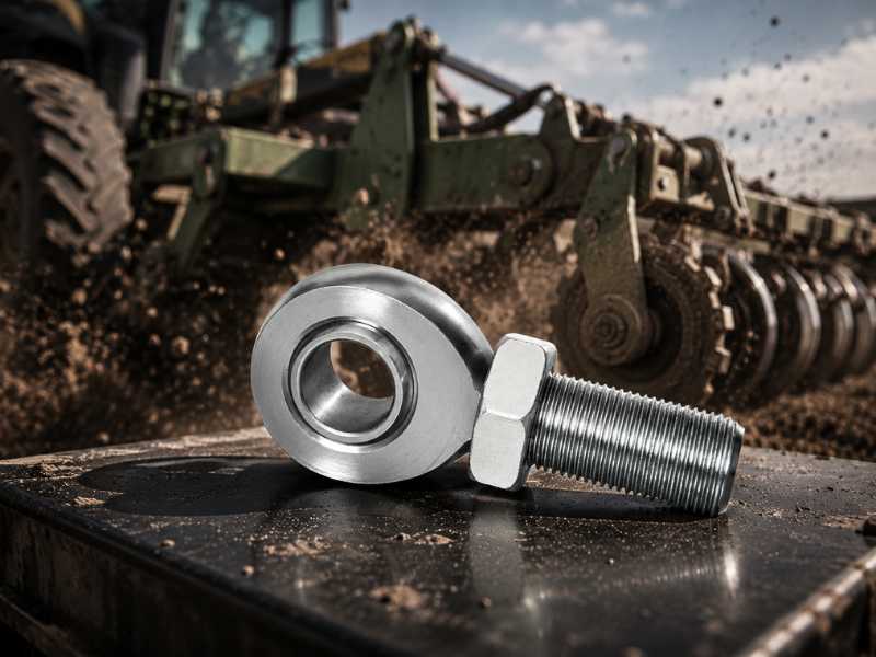
A rod end that is correctly sized for its nominal working load fails ahead of schedule in one consistent pattern: the nominal load was used for selection, but the actual load peaks were not. Shock loads are brief. They are also multiples of the steady-state force, and they arrive at a rate the dynamic load rating of a rod end is not designed to absorb.
This article covers where shock energy concentrates in a rod end, the four damage modes that follow, and the load rating math that determines whether a given joint survives.
Why the Dynamic Rating Does Not Cover Shock
The dynamic load rating on a rod end data sheet is calculated for continuous oscillating or rotating contact under steady load. It predicts bearing life in hours or cycles at that sustained level. A shock event is structurally different: it is a high-amplitude transient that lasts milliseconds and imposes contact stresses that can exceed the static limit in a single event.
When dynamically loaded bearings are subjected to heavy shock loads, the static load rating governs, not the dynamic one. The static radial load rating (C0) represents the load at which permanent deformation of the ball or race surface begins. The static radial ultimate load, which is approximately 1.5 times the limit load, is the threshold above which fracture of the ball, race, or rod end eye occurs.
For applications with potential severe shocks, a static safety factor (S0) of 5 to 6 is recommended. Most engineers selecting rod ends apply the dynamic rating with a modest safety factor of 1.5 to 2. In shock-loaded applications, that approach is insufficient by a factor of three to four.
The consequence of using dynamic rating alone for shock selection is not gradual wear. It is one of four discrete damage modes, each with a different signature and a different root cause.
Damage Mode 1: Brinelling of the Ball or Race
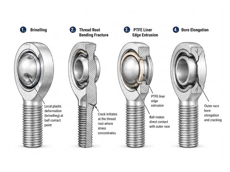
When a shock load drives contact stress above the static limit, the ball or the housing race surface undergoes localized plastic deformation. The result is a shallow indentation at the contact point, a phenomenon called brinelling from its resemblance to the Brinell hardness test impression.
In a rod end, brinelling appears as a flat spot or pit on the ball surface aligned with the load axis. Once present, it is irreversible. Every subsequent oscillation of the joint passes the ball across that indentation, generating a repeating impact that accelerates liner wear and produces audible clicking or knocking under load.
Stainless steel balls (304, 316) are more susceptible to brinelling than hardened 52100 chrome steel balls because austenitic stainless has a lower yield strength at the contact surface. For shock-loaded applications in corrosive environments where stainless is specified for grade reasons, selecting a rod end with a 17-4PH or 440C stainless ball rather than 304/316 increases the contact fatigue resistance substantially without sacrificing corrosion performance.
Damage Mode 2: Shank Fracture at the Thread Root
Shock loads applied at an angle to the rod end bore axis generate bending moments at the shank. The critical location is the thread root immediately adjacent to the housing face, where the stress concentration factor from the thread geometry combines with the bending moment from the offset load.
This failure mode is accelerated by two common installation conditions. The first is installing the rod end off-axis to make up for a misaligned mounting, then preloading the shank into a bent position. The shank carries a static bending stress before any service load arrives, and the shock load adds to a section that is already stressed. The second is an undersized bolt through the ball bore that allows the joint to rattle under load reversals, generating small but repeated bending impulses at the shank root.
Shank fracture is the most abrupt failure mode in shock-loaded rod end assemblies. There is typically no visible warning before separation.
Damage Mode 3: PTFE Liner Shear and Extrusion
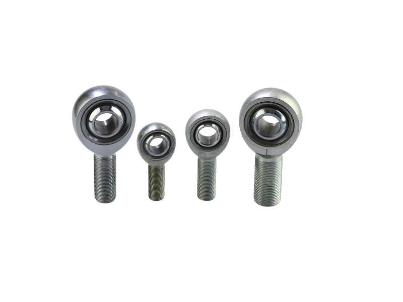
Self-lubricating rod ends with PTFE composite liners are the standard for most industrial and corrosion-environment applications. The liner occupies the clearance between the ball and the housing bore and provides the low-friction, maintenance-free operation that makes them practical.
Under shock loading, the liner behaves differently than it does under steady load. A sustained radial force compresses the PTFE liner uniformly across the contact zone. A shock load applies the same force magnitude in a fraction of the time, generating a pressure spike that can cause the liner material to shear at the edges of the contact zone or extrude out of the housing bore clearance. Once the liner has extruded or sheared, the ball contacts the housing race directly. The joint does not immediately seize, but wear rate accelerates sharply and the maintenance-free characteristic is lost.
Liner failure from shock is distinguished from liner wear by the location of material loss. Normal wear thins the liner gradually across the full contact band. Shock extrusion removes material at the perimeter of the contact zone while the center remains intact.
For applications where shock is predictable and frequent, metal-to-metal (greased) rod ends with hardened chrome steel or stainless contact surfaces outlast PTFE-lined units. The maintenance interval required for a greased joint is a known trade-off against the unpredictable replacement schedule of a PTFE joint in shock-loaded service.
Damage Mode 4: Housing Eye Deformation and Bore Elongation
The housing eye of a rod end is a thin-walled ring loaded in tension across the bore when radial load is applied. Static load ratings account for the housing material strength under that tension. A shock load imposes the same tension pattern at high strain rate, and the thin section at the equator of the eye is the failure location.
In mild overload events, the eye deforms elastically and returns. In moderate shock events that exceed the static limit load but not the ultimate load, permanent plastic deformation widens the bore slightly. The ball then has radial play it did not have before, and subsequent load cycles rock the ball in the enlarged bore, accelerating wear at the liner edges.
In severe events that approach the ultimate load rating, the housing eye cracks at the equator or separates completely. This is the catastrophic failure mode of the housing rather than the shank or liner.
Cast or sintered rod end housings are disproportionately vulnerable to this failure mode because casting porosity acts as a crack initiation site under the high strain rates of shock loading. Machined housings from bar stock have a uniform, pore-free structure that provides better resistance to shock-induced fracture. For shock-loaded applications, specifying machined rod end housings rather than cast is worth the cost premium.
How to Apply the Shock Factor Correctly
The standard method for accounting for shock in rod end selection uses a shock factor (also called a service factor or application factor) multiplied against the maximum expected operating load. The product is the equivalent static load used for bearing selection against the C0 rating.
Shock factor values by application type:
Smooth, vibration-free operation with no shock: factor 1.0 to 1.5. Moderate shock with occasional load spikes up to twice the nominal: factor 2.0 to 3.5. Heavy shock, impact loads, abrupt direction reversals: factor 3.5 to 5.0. Extreme shock, end-of-travel impact without cushioning, agricultural implement striking buried obstacles: factor 5.0 to 6.0 or higher.
The selection criterion is: C0 (kN) is greater than or equal to shock factor multiplied by maximum operating load (kN). If the catalog C0 of the candidate rod end does not satisfy this inequality, select the next size up or change the housing material to a higher-strength alloy.
For stainless steel rod ends, note that the C0 values published in catalogs are typically lower than equivalent-geometry chrome steel rod ends because of the lower yield strength of austenitic grades. A 316 stainless rod end in M16 will have a lower C0 than a 52100 chrome steel rod end in the same housing size. When shock factor calculations push the required C0 above what the stainless configuration can deliver, the design options are: increase to the next housing size, switch the ball material to 17-4PH, or add a shock absorber or damper elsewhere in the load path to reduce the peak load reaching the rod end.
Mounting Configuration and Shock Direction
The direction of the shock load relative to the rod end bore axis significantly affects which failure mode dominates. A radial shock directly across the bore axis loads the housing eye in tension and the ball-to-liner interface in compression. This is the configuration for which load ratings are published and shock factors apply directly.
An axial shock along the bore axis loads the retention of the ball within the housing. The axial load capacity of a rod end is typically 10 to 20 percent of its radial capacity, depending on whether the design is two-piece or three-piece and how the ball is retained. An assembly that positions the rod end such that shock loads arrive predominantly along the bore axis rather than across it is misapplying the joint, regardless of what the radial rating calculation shows.
Compound loads (simultaneous radial and axial components) require vector addition of the two load components before applying the shock factor. Using the radial load alone for selection when an axial component is present underestimates the equivalent load and under-sizes the joint.
When shock direction is predictable, orient the stainless steel rod end housing so the dominant shock vector aligns with the rated radial axis, then separately verify the axial component against its published rating. This applies to hydraulic cylinder end caps, agricultural top links, and marine steering linkages.
What Changes When the Material Is Stainless
Stainless steel rod ends introduce two shock-specific considerations that carbon steel rod ends do not.
First, work hardening under shock. Austenitic stainless (304, 316) work-hardens rapidly under plastic deformation at high strain rates. A shock event that causes brinelling or shank thread deformation leaves the affected zone harder and more brittle than the surrounding material. Subsequent shock events at the same location encounter a work-hardened surface with reduced ductility and crack more readily. This progressive embrittlement is not visible without metallographic inspection and is not reflected in catalog load ratings.
Second, corrosion at the damage site. Once brinelling or liner extrusion exposes the base metal at the ball or race surface, the passive chromium oxide layer is disrupted at that location. In marine, food processing, or chemical environments, corrosion initiates at the damaged zone faster than it would on an undamaged surface. The damage from a single shock event accelerates both mechanical wear and corrosion simultaneously.
Specifying 316 over 304 for shock-loaded applications in corrosive environments does not improve the mechanical shock resistance directly. The molybdenum content in 316 improves corrosion resistance at the damaged zone after a shock event, slowing the combined wear-corrosion failure that follows. That secondary benefit is worth the grade premium in environments where both shock and corrosion are present.
Profab Machine manufactures stainless steel rod ends in 304, 316L, and 17-4PH, sized and rated against the actual shock factor your application requires, not just the nominal load. Machined housings are available where cast construction isn't suitable for shock-loaded service.