- By Ray Wang /
- May 29, 2026
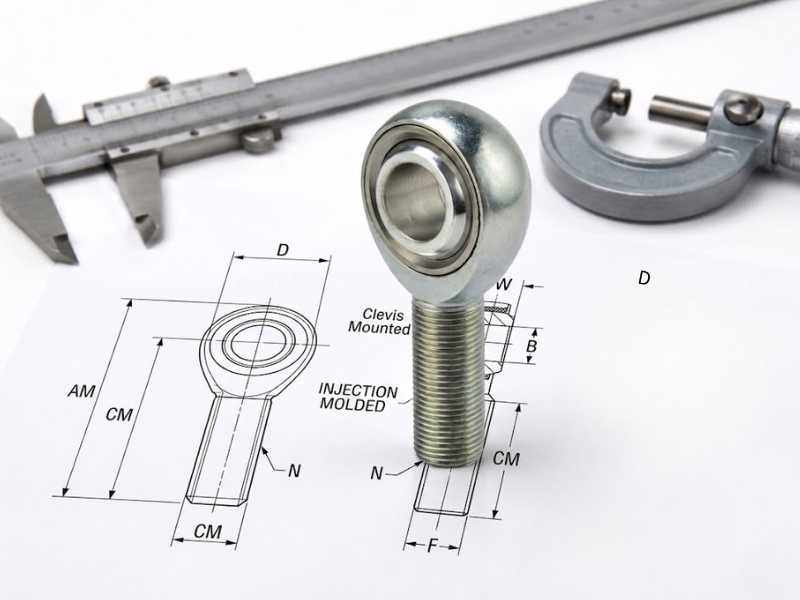
Table of Contents
Ordering a replacement rod end by thread size alone produces the wrong part more often than it should. Two rod ends with identical thread specifications can differ in bore diameter, body width, and housing OD by enough to prevent fit or function in the original mounting. The thread size tells you how the shank attaches. It says nothing about how the joint connects at the other end, how much axial space it occupies in the bracket, or whether the ball will physically clear the chassis at full suspension travel.
Seven dimensions define a rod end completely. Under ISO 12240-4, each has a standard designation. Knowing both the measurement method and the designation lets you specify unambiguously when ordering custom or replacement parts.
The Tools You Need Before Starting
A digital caliper with 0.01 mm or 0.001 inch resolution is the only tool that produces reliable results for rod end measurement. A steel rule introduces enough parallax error to misread a bore diameter by 0.5 mm, which is the difference between a snug pin fit and a sloppy one. A thread pitch gauge is the second tool, used only to confirm pitch after the thread diameter is known.
Dimension 1: Bore Diameter (d)
The bore is the hole through the center of the ball that accepts the pivot shaft. Under ISO 12240-4, this nominal diameter is designated as d.
Measure with the inside jaws of the caliper across the bore interior. Take two readings at 90 degrees to each other. If the two readings differ by more than 0.05 mm, the bore is out of round from wear and the joint should be replaced rather than reused.
The nominal bore diameter is the number you see in catalog listings (10 mm, 12 mm, 1/2 inch). What catalogs do not always state is the tolerance class. A bore specified as H7 fits a shaft at close clearance with minimal lateral play. H9 gives a looser fit with measurable clearance, which is acceptable for slow-pivot structural applications but audible as a knock in dynamic linkages. When ordering replacements, specify bore diameter and tolerance class together. Nominal alone leaves the manufacturer to apply their default, which may not match the original.
Dimension 2: Thread Size and Pitch (d3 or G))
For male rod ends, measure the outside diameter across the thread crests. Note that due to standard thread tolerances, an M12 thread will typically measure slightly undersized (e.g., 11.85 mm). Round up to the nearest nominal standard.
Metric threads are expressed as diameter times pitch: M12 x 1.75. Inch threads are expressed as diameter times threads-per-inch in UNF or UNC: 1/2-20 UNF. The thread series (UNF versus UNC) matters because a 1/2-20 UNF shank will not engage a 1/2-13 UNC tube end, even though the diameter is identical.
For female rod ends (threaded bore in the body), the measurement sequence is the same but uses a thread gauge pin or internal thread gauge to confirm the bore diameter and pitch of the body thread rather than a shank. The bore diameter of the body thread is distinct from the bore of the ball.
Dimension 3: Thread Hand
Thread direction is not measurable with a caliper. It requires a physical check: rotate the shank into a known right-hand nut. If it engages clockwise, it is right-hand. If it engages counter-clockwise, it is left-hand.
Left-hand rod ends carry a machined circumferential groove on the shank hex or adjacent to the thread as the standard identification mark. If no groove is present and no LH marking is stamped, confirm by trial with a known RH fitting before assuming direction. Installing a LH rod end into a RH tube end produces no engagement, which is immediately obvious. The error that causes real damage is assuming RH and torquing hard before resistance signals the mismatch.
Dimension 4: Inner Ring Width (B) and Body Width (C)
Do not confuse the housing body thickness with the ball’s inner ring width. The inner ring width (B) is the axial thickness across the flat faces of the ball itself. This dictates the gap required inside your mounting clevis. The body width (C) is the thickness of the outer housing ring. Both must be verified to ensure proper spacing and prevent the housing from binding against the bracket under torque.
Dimension 5: Housing Outside Diameter (d2)
Housing OD is the outer diameter of the housing ring. Measure across the widest point of the housing using outer jaws. This dimension determines whether the joint clears surrounding structure at full misalignment.
Housing OD is not standardized across manufacturers at equivalent thread sizes. Two M12 rod ends from different suppliers can have housing ODs that differ by 2 to 3 mm. In close-clearance installations, measure the OD of the joint you intend to replace and confirm the replacement matches before ordering in quantity.
Dimension 6: Center Height / Length to Bore Center (h or l3)
Head radial height determines outer clearance, but the critical installation dimension is the Center Height (h)—the distance from the precise center of the bore to the base of the housing shoulder or shank end. To measure this accurately without specialized fixed-center gauges: measure from the shank end face to the closest edge of the inner bore using the caliper’s outer jaws, then add half of your measured bore diameter (d/2).
Dimension 7: Overall Shank Length (l1) and Thread Engagement Length (l2)
Overall shank length is the distance from the housing face to the tip of the threaded shank, measured along the shank axis. Thread engagement length is the threaded portion of that shank, from the first full thread to the housing shoulder.
Both dimensions matter for installation. Thread engagement length determines how deep the shank can be screwed into the tube or coupling, which sets the available adjustment range. A shank with 25 mm of thread engagement in a tube that requires 30 mm of minimum thread depth is undersized for that application regardless of how the bore and thread diameter measure.
Dimension 8: Misalignment Angle
Misalignment angle is the maximum angular deviation the ball can rotate from the bore axis before the shank or housing contacts a stop. It is measured by rotating the ball manually to its physical limit and reading the angle with a digital inclinometer or by geometric calculation from the housing opening geometry.
Standard rod ends offer 12 to 18 degrees of misalignment. High-misalignment configurations reach 25 to 34 degrees. If the application requires 20 degrees of travel and the joint measures 14 degrees at the limit, adding misalignment spacers or replacing with a high-misalignment rod end is the fix. Running a joint beyond its rated misalignment angle causes edge loading of the liner at the housing rim, which accelerates wear at a specific line across the ball surface rather than distributing it across the contact band.
What to Specify When Ordering Custom Rod Ends
For replacement orders where you are matching an existing joint, the minimum specification is: bore diameter with tolerance class, thread size with pitch and hand, body width, and overall shank length. Housing OD and head radial height allow confirmation that the joint clears surrounding structure.
For OEM orders to drawing, ISO 12240-4 provides the full dimensional framework. The standard defines dimensions d, d1, d2, d3, b, c, and l with tolerance classes for each, along with static and dynamic load ratings that allow load calculation rather than estimation. A purchase order that references ISO 12240-4 with the relevant size designation gives the manufacturer an unambiguous dimensional target and a traceable basis for inspection.
When sourcing stainless steel rod ends for food processing, marine, or industrial applications, request that the tolerance class for the bore and the thread be confirmed in writing with the order acknowledgment. Grade alone (304 or 316) does not specify the fit. The fit is a separate variable, and it determines whether the joint performs correctly in the application.

Ray Wang is an engineer at our company with more than 20 years of experience in stainless steel applications and automotive parts. Over the years, he has built deep expertise in precision machining, material behavior, and practical engineering solutions. His hands-on background and strong focus on quality help ensure every project meets demanding performance and reliability standards.
Ray Wang is an engineer at our company with more than 20 years of experience in stainless steel applications and automotive parts. Over the years, he has built deep expertise in precision machining, material behavior, and practical engineering solutions. His hands-on background and strong focus on quality help ensure every project meets demanding performance and reliability standards.
Send Inquiry Now
Related Resource

Pitting Corrosion in Marine Rod Ends
How Shock Loads Damage Rod Ends
How Opposite Threads on Rod Ends Enable Adjustment