
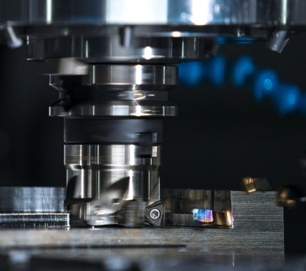
Design a stainless steel part with walls of at least 1.5 mm and a height of no more than 8 times the thickness. Make inside corners at least one third of the pocket depth, pockets no deeper than 4 times their width, and threads no longer than 3 times the diameter. The wall minimum, the thread engagement and the thread relief are the stainless-specific figures. The rest are general milling limits, which a 304 or 316 part should treat as ceilings and not as targets.
| Feature | Recommended limit | Basis |
|---|---|---|
| Wall thickness | 1.5 mm; 1.0 mm is the feasible minimum | Stainless figure |
| Wall height to thickness | 8:1 or less | Published wall guide |
| Inside vertical corner radius | One third of pocket depth or more | General milling |
| Pocket depth | Up to 4 times pocket width, for chip evacuation | General milling |
| Hole depth | 4 times diameter recommended; 10 times typical | General milling |
| Thread length | 1.5 times diameter minimum; 3 times recommended, for load distribution | General milling |
| Thread engagement | 50 to 60 percent | Hard materials including stainless |
The wall figures are from a published wall thickness guide, which lists 1.5 mm as the standard minimum for stainless steel against 0.8 mm for aluminium, and 1.0 mm as the feasible minimum.
The corner, pocket, hole and thread-length limits are general milling guidance from a published CNC design guide, not stainless-validated figures. Use them as the starting point for a drawing review.
Why Stainless Is Harder to Cut
The wall guide gives higher hardness and cutting forces as the reason stainless needs a thicker wall than aluminium. A published stainless machining guide adds that a pass that does not cut deep enough leaves a hardened skin, and the next pass has to cut through metal harder than the parent material.
The same guide gives stainless a thermal conductivity of 15 to 30 W/m·K, against 30 to 60 for carbon steel and 237 for aluminium. Heat leaves less readily through the part, so the guide keeps cutting speed conservative and warns that high speed raises temperature and shortens tool life.
For a drawing, that means keeping walls and ribs at or above the stainless minimum and avoiding features that force a very light cut. If a thin section cannot change, such as a sealing lip, flag it on the drawing so the shop plans support for it.
Check the Wall Before You Release the Drawing
Divide the wall height by its thickness and keep the result at 8 or below. The wall guide lists 1.0 mm walls up to 8 mm tall, 2.0 mm walls up to 16 mm and 3.0 mm walls up to 24 mm. A 1.5 mm wall that is 15 mm tall gives 10:1, so thicken it to 2.0 mm, which brings it to 7.5:1.
The same guide lists the ways out when the wall cannot be thickened: add ribs or gussets, reduce the unsupported height, increase the inside corner radii, or split the part into pieces that are assembled.
Machine Thin Walls Without Chatter
A wall that passes the 8:1 check can still chatter during machining, because it loses stiffness with every pass. A thin wall has a low natural frequency, which is what chatter excites. Stainless adds to the problem because 304 and 316 work-harden and give higher cutting forces, and the wall loses stiffness as material comes off, so the last passes tend to be the riskiest.
Tool setup comes first. Use the largest tool the feature allows with the shortest practical overhang, and a sharp positive-rake carbide tool, which lowers the cutting force on the wall. A published thin-wall guide puts the finishing radial depth at 10 to 15 percent of the tool diameter, not a full-width final cut.
Clamping matters as much as cutting. Heavy local clamping pressure distorts the part before the cutter touches it. The wall springs back when the clamp releases, so a wall that measured correctly on the machine can be out of tolerance on the bench. Soft jaws spread the pressure, and a vacuum fixture avoids local loading on a part with a flat back face. Finish both faces in alternation to balance the cutting forces on the wall, and if chatter remains, change the spindle speed to move the tooth-engagement frequency away from the wall's natural frequency.
Size Corner Radius From Pocket Depth
An inside corner cannot be sharper than the cutter that makes it. The design guide sets the radius at one third of the pocket depth or more. A 12 mm deep pocket needs a radius of at least 4 mm, and an 18 mm deep pocket needs 6 mm. A small floor radius of 0.5 or 1 mm, or none, is the recommended bottom edge.
The depth limit of 4 times the pocket width is given for chip evacuation, so a 10 mm wide pocket stops at 40 mm. If the mating part has a sharp outside corner, chamfer or relieve it so it seats in the radius.
Specify Threads That Stainless Can Take
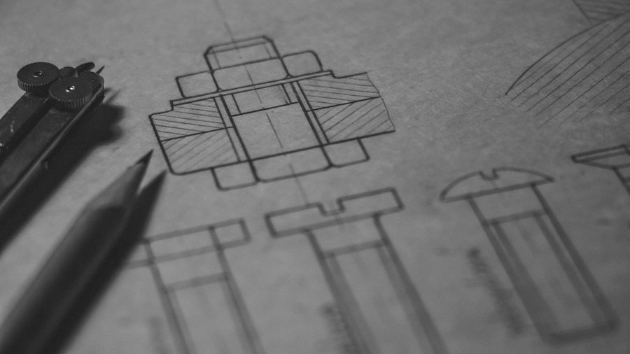
The design guide gives 1.5 times the nominal diameter as the minimum thread length and 3 times as the recommended length, with M6 or larger as the recommended size. A longer thread adds machining time.
A tap selection guide says about 90 percent of the thread's shear strength is developed at 60 percent engagement and that going from 60 to 75 percent adds very little. For 304 and 316 it advises dropping to 55 to 60 percent, because stainless work-hardens during cutting and tapping torque rises as the tap advances. Specifying 50 to 60 percent therefore costs little strength and lowers the risk of a broken tap.
A tapped-parts guide gives the same 50 to 60 percent for hard materials such as stainless steel, against 70 to 75 percent for soft ones. For a blind hole, it adds at least 3 pitches of drilled depth beyond the thread for chip relief, and the stainless machining guide gives 2 to 3. For an M8 × 1.25 blind thread of 12 mm, a 3-pitch relief means a drilled depth of about 16 mm.
Thread milling is the better choice over tapping in stainless, according to the stainless machining guide, and neat cutting oil is the lubricant it names for tapping. The tapped-parts guide asks for a smooth pilot hole in the CAD model, not modelled thread geometry, so show the thread as a callout (M8 × 1.25-6H, 12 mm deep).
Prevent Thread Galling in Stainless Assemblies
A fastener distributor's guide calls stainless fasteners particularly susceptible to galling, where pressure breaks down the protective oxide film and the surfaces fuse. Its remedies are thread lubrication, lower installation speed, coarse threads with a 2A-2B fit instead of fine threads, and smoother thread surfaces, noting that rolled threads are usually smoother than cut ones.
It also says mating parts of the same alloy gall more readily than dissimilar alloys. A fastener maker's guide gives the same remedy of using different stainless grades for bolt and nut, and adds that the nut must always be stronger than the bolt. In a tapped hole the part's thread acts as the nut, so the screw should not be the stronger of the two.
On the assembly drawing, call out a thread lubricant and the screw grade. Where a 304 screw would run into a 304 part, consider a dissimilar screw grade that is not stronger than the part.
Choose the Grade for How You Machine and Use the Part
Grade changes cost as much as geometry. A published machinability table rates the grades against free-machining carbon steel as 100 percent.
| Grade | Machinability rating | Trade-off |
|---|---|---|
| 303 (annealed) | 78% | Sulfur improves chip breaking, but corrosion resistance and weldability are lower |
| 304 (annealed) | 45% | Standard chromium-nickel grade, rated 45% |
| 316 (annealed) | 45% | Molybdenum adds chloride resistance; rated the same as 304 in this table |
| 17-4PH (condition A) | 48% | Hardened by aging, with a size change (see the 17-4PH section) |
Ratings differ between published tables: the stainless machining guide lists 316 at 40 percent and 17-4PH at 30 percent, so use the numbers to rank grades and not to predict a cycle time. A published grade comparison states that 303 machines much better while 304 resists corrosion better and welds much better. Use 303 only for a part that is not welded and does not see wet or chloride service.
Allow for 17-4PH Size Change After Aging
A part machined in 17-4PH condition A shrinks when it is aged. A machining trade cribsheet gives a contraction of 0.0004 to 0.0006 in/in from condition A to H900, and about 0.0009 to 0.0012 in/in to H1150, because the metal undergoes a volume contraction when hardened.
On a 100 mm dimension, that is 0.04 to 0.06 mm at H900 and 0.09 to 0.12 mm at H1150. Both are far larger than a ±0.01 mm tolerance. So the drawing must say whether a tight feature is finished after aging, or machined to a size that allows for the change, and which condition the part is delivered in.
Finishing Changes Size, and Not Every Finish Does
Passivation removes free iron and restores the passive layer without changing part dimensions, according to a finisher's FAQ. Electropolishing removes a thin, uniform layer of metal by anodic dissolution, so it does change them.
Put the finished size on the drawing for a part that will be electropolished, and agree the removal with the finisher. State the edge break as well: a published edge guide recommends a range such as "Break all sharp edges 0.2 to 0.5", and warns that missing edge specs create rework and scrap. Leave the default as-machined finish of Ra 3.2 µm unless a function needs better; the stainless machining guide advises against specifying an ultra-smooth finish without a functional reason.
Tight tolerances are the other major cost driver and have their own limits. Our guide to CNC tolerances on stainless steel gives the tiers and the fit tables. The stainless machining guide recommends a general class m tolerance in the title block for every dimension that carries no tolerance of its own.
Worked Example: Reviewing a 304 Bracket
This is a worked review of a drawing against the limits above. The bracket has a 1.5 mm wall 15 mm tall, an 18 mm deep pocket 30 mm wide with sharp corners, and an M8 × 1.25 blind thread 12 mm deep.
| Feature | As drawn | Check | Change |
|---|---|---|---|
| Wall | 1.5 mm thick, 15 mm tall | Ratio 10:1, over the 8:1 limit | Thicken to 2.0 mm, giving 7.5:1 |
| Pocket corners | Sharp | Radius must be 18 / 3 = 6 mm or more | Add R6 inside vertical corners |
| Pocket depth | 18 mm in 30 mm width | 18 / 30 = 0.6, under the 4:1 limit | No change |
| Blind thread | M8 × 1.25, 12 mm deep | 12 / 8 = 1.5 diameters, within range; relief 3 × 1.25 = 3.75 mm | Drill to 16 mm; callout M8 × 1.25-6H |
| Assembly | 304 screw into 304 part | Same alloy mates gall more readily | Call out thread lubricant; consider a dissimilar screw grade not stronger than the part |
The review changes two dimensions and adds one callout.
What to Send With a Drawing
A drawing with these details lets us quote the part as it is and flag any limit it crosses:
- Wall thickness and height wherever a wall is under 2 mm
- Pocket depth, inside corner radius, thread callouts and blind-hole depths
- Material grade and condition (for example 17-4PH H900), and whether the part will be welded or sit in a wet environment
- Surface finish, passivation or electropolishing, the finished size and the edge break
- The two or three critical dimensions, with the general tolerance on everything else
Conclusion
Keep walls at 1.5 mm or more and 8:1 or less, and size inside corners from pocket depth. Specify threads as callouts with a relief, and choose the grade and heat treatment condition for both machining and service. If you are looking for a new supplier of custom stainless steel CNC parts, send your drawing to Profab Machine and we will flag any limit it crosses before we quote.