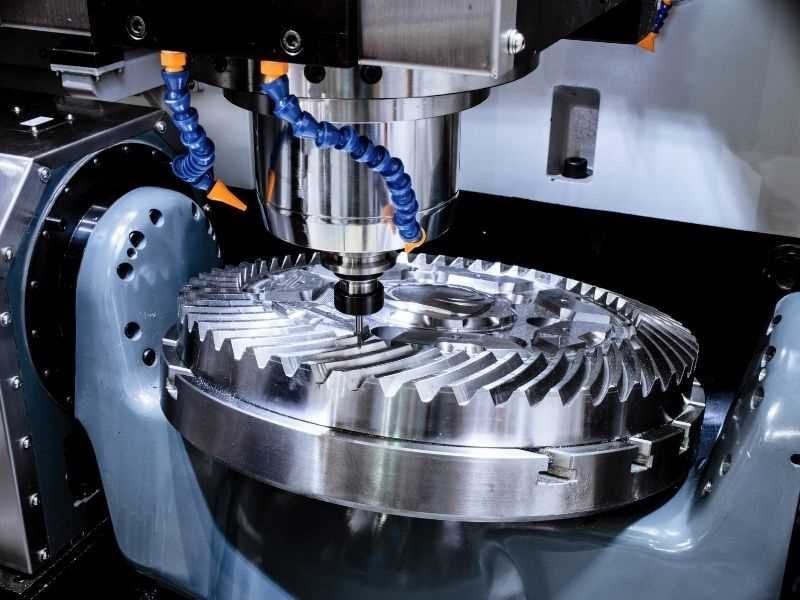
A CNC shop typically holds about ±0.1 mm (±0.004 in) on stainless steel features without special effort. It holds ±0.025 to ±0.05 mm (±0.001 to ±0.002 in) on features you mark, and ±0.01 mm (±0.0004 in) on a few critical features that need a closer look at process and inspection. Each step tighter costs more, so the practical job is to tighten only the features that need it.
| Tolerance tier | Typical value | Use it for | Relative cost |
|---|---|---|---|
| Standard | ±0.1 to ±0.125 mm ±0.004 to ±0.005 in | Clearance holes, non-mating faces, overall dimensions | 1x |
| Tight | ±0.025 to ±0.05 mm ±0.001 to ±0.002 in | Bearing press fits, dowel holes, mating parts | 1.5x to 2x |
| Precision | ±0.01 mm or tighter ±0.0004 in or tighter | Seal faces, precision shafts | 4x or more |
The tiers and cost multiples come from one published cost guide, which places grinding at the precision tier. Treat the multiples as the shape of the cost curve, not as a quote. In our practice stainless steel sits at the cautious end of each tier, for the reasons in the next sections. The baseline numbers behind the tiers (process capability, ISO 2768, ISO 286 fits) follow them.
Profab Machine machines features to ±0.01 mm. At that tier we review the feature, its size and the grade before quoting, because the route (machining alone or a finishing step) depends on them.
Why Stainless Is Harder to Hold Than Other Metals
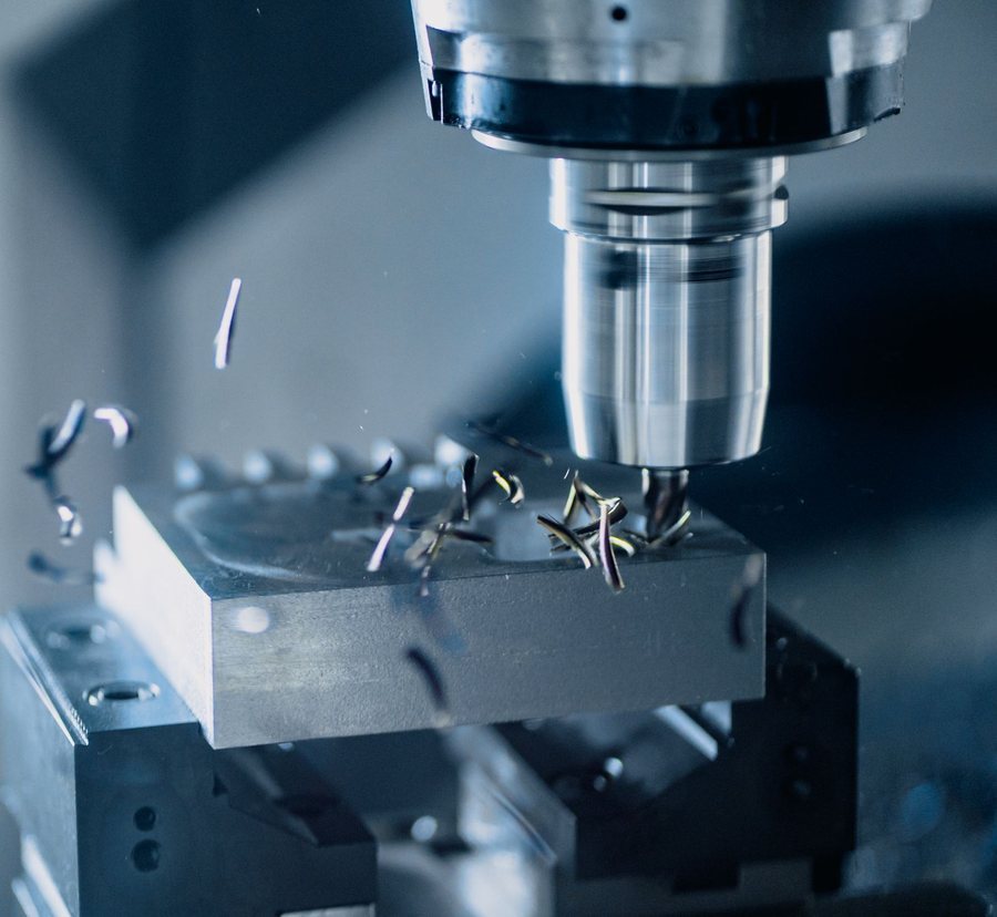
Austenitic stainless grades such as 304 and 316 work-harden under the cut and conduct heat poorly. The dimension can then drift from the first part to the last. A published stainless machining guide gives the mechanism. If a pass is not cutting cleanly, the next pass meets a harder layer than planned, so the guide asks for steadier feeds, sharp inserts and lighter finishing cuts.
The same guide notes that a long run slowly shifts as heat, insert wear and clamping stress change, and the remedy is regular offset checks during the run. For a ±0.01 mm feature that means the process is not set once at the start. It is checked part by part, and that is where the cost multiple in the tier table comes from.
Temperature alone matters at ±0.01 mm. Type 304 expands 9.6 µin/in/°F, which is about 17.3 µm per meter per kelvin, from a published expansion table. A 50 mm feature that is 10 K warmer than its reference temperature grows by 50 × 17.3 × 10 / 1000 = 0.009 mm. That uses most of a ±0.01 mm tolerance.
How the Grade Changes What You Can Hold
The grade you order changes how easily a tight size is held, so name the grade before you set the tolerance.
303 Stainless
303 is the easiest grade for a tight size and a fine finish. Added sulfur or selenium breaks the chip, which keeps the cut steady, and the price is slightly lower corrosion resistance than 304. In one published comparison 303 is rated 78% and 304 is rated 45% on machinability. Percentages from different sources are not directly comparable, but the order is consistent.
304, 316 and 316L Stainless
304 is the reference grade for the tiers in this article, and it work-hardens, so the tool needs a steady cut. 316 and 316L machine much like 304, with a slightly lower rating in most published tables. We usually plan the same tier as 304 and confirm the tight features before quoting.
17-4PH machines in the annealed condition and shrinks when it is aged, which is covered under heat treatment below.
Galling Limits How Tight a Running Fit Can Go
A tighter running fit is not always a better one on stainless steel, because stainless against stainless can gall. The passive oxide layer on austenitic grades is only a few nanometers thick, and contact stress can break it faster than it reforms. Bare metal then touches bare metal and cold-welds at the high points. Our thread galling guide explains the mechanism.
An H7/g6 running fit at 18 to 30 mm (fit bands are tabulated below) leaves 7 to 41 µm of clearance. Taking the clearance toward zero to remove play makes a dry stainless pair more likely to seize. Before tightening the fit, keep grease or a lined bushing in the joint, or pair the shaft with a different alloy or hardness. Our bushing fit guide shows which fit pairs suit a stainless bushing.
Heat Treatment and Finishing Change the Size
Any process after machining can move the final dimension, so the tolerance has to be met after the last step, not after the cutting.
Aging 17-4PH
17-4PH contracts when it is aged from the annealed condition. A machinist's reference sheet gives 0.0004 to 0.0006 in/in for annealed to H900 and 0.0009 to 0.0012 in/in for annealed to H1150. On a 100 mm feature that is 0.04 to 0.06 mm at H900 and 0.09 to 0.12 mm at H1150. Either number is as large as, or larger than, the whole 0.05 mm band of a ±0.025 mm tolerance. The part is therefore machined oversize and finished after aging, or the allowance is built into the pre-aging size.
Passivation and Electropolishing
Passivation removes surface contaminants, and any dimensional change is typically negligible next to electropolishing. Electropolishing does remove metal: NASA's electropolishing specification sets metal removal at 0.0002 to 0.0005 in (5 to 13 µm) per surface. An outside diameter therefore shrinks by twice that, 10 to 25 µm. On a 20 mm h6 shaft with a 13 µm band, the top of that range uses almost two full tolerance bands. Agree the removal with the finisher first, and put the finished size on the drawing.
Baseline Numbers: Process, General Tolerance and Fits
These are general CNC and ISO values, not stainless-specific ones. Use them to see which operation a tolerance forces and how wide a fit band is, then apply the stainless limits above.
Tolerance by Process
The process that finishes a feature sets the tolerance it can hold. The figures are from a published CNC tolerance chart.
| Process | Standard | Precision |
|---|---|---|
| Milling | ±0.13 mm (±0.005 in) | ±0.025 to ±0.051 mm (±0.001 to ±0.002 in) |
| Turning | ±0.13 mm (±0.005 in) | ±0.025 mm (±0.001 in) |
| Drilling | ±0.13 mm (±0.005 in) | ±0.051 mm (±0.002 in) |
| Reaming | ±0.025 mm (±0.001 in) | ±0.013 mm (±0.0005 in) |
| Boring | ±0.025 to ±0.051 mm (±0.001 to ±0.002 in) | ±0.013 mm (±0.0005 in) |
| Grinding | ±0.013 to ±0.025 mm (±0.0005 to ±0.001 in) | Below ±0.013 mm (below ±0.0005 in) |
A drilled hole is only good to about ±0.13 mm, so a bearing seat or dowel hole must be reamed or bored after drilling. In 304 and 316 a drill that rubs instead of cutting can leave a work-hardened wall, so the reamer or boring tool should take a clean, positive cut. A turned outside diameter reaches ±0.025 mm, but a 20 mm h6 shaft has a total band of 13 µm (about ±0.0065 mm), which takes grinding or a fine finishing pass.
Converting a drawing in inches: 1 in = 25.4 mm, so ±0.005 in is ±0.127 mm, ±0.001 in is ±0.0254 mm and ±0.0005 in is ±0.0127 mm. A callout of ±0.0001 in (2.5 µm) is beyond what a normal turning or milling setup holds.
General Tolerance in the Title Block
Write the general tolerance class on the drawing, so every dimension without its own tolerance has a defined limit. ISO 2768-1 sets four classes (f, m, c and v); the values below are the permitted deviation in mm for the three most used, from a published ISO 2768 table.
| Nominal size | Fine (f) | Medium (m) | Coarse (c) |
|---|---|---|---|
| 0.5 up to 3 mm | ±0.05 | ±0.1 | ±0.2 |
| Over 3 up to 6 mm | ±0.05 | ±0.1 | ±0.3 |
| Over 6 up to 30 mm | ±0.1 | ±0.2 | ±0.5 |
| Over 30 up to 120 mm | ±0.15 | ±0.3 | ±0.8 |
| Over 120 up to 400 mm | ±0.2 | ±0.5 | ±1.2 |
Marking the class as ISO 2768-m on a 20 mm feature allows ±0.2 mm. If that feature must close on a bearing, it needs its own tolerance.
IT Grades and the H7/h6 Fit
Fits use ISO 286 tolerance grades, written IT6, IT7 and so on. The grade sets the width of the band, and that width grows with the size of the feature. For an H7 bore running on an h6 shaft, the clearance always starts at zero and ends at the sum of the IT7 and IT6 bands. The widths below are from the published ISO 286 grade table.
| Nominal size | IT6 (µm) | IT7 (µm) | IT8 (µm) | H7/h6 clearance (µm) |
|---|---|---|---|---|
| 6 to 10 mm | 9 | 15 | 22 | 0 to 24 |
| 10 to 18 mm | 11 | 18 | 27 | 0 to 29 |
| 18 to 30 mm | 13 | 21 | 33 | 0 to 34 |
| 30 to 50 mm | 16 | 25 | 39 | 0 to 41 |
| 50 to 80 mm | 19 | 30 | 46 | 0 to 49 |
| 80 to 120 mm | 22 | 35 | 54 | 0 to 57 |
A 20 mm bore toleranced H7 runs from 20.000 to 20.021 mm, and a 20 mm shaft toleranced h6 runs from 19.987 to 20.000 mm. At 18 to 30 mm the H7 band is 0.021 mm wide. That is narrower than the 0.026 mm band of a precision reamed or bored hole (±0.013 mm), so the chart's precision column does not guarantee an H7 bore. H7 is a one-sided band from 0 to +0.021 mm. The shop aims at the middle, about +0.0105 mm, and checks the finished bore with a gauge.
Position, Stack-Up and Measurement
A size tolerance alone does not control shape or location. Position shows the difference. A hole located by ±0.1 mm in X and Y lets its center sit in a 0.2 mm square, whose corner is √(0.1² + 0.1²) = 0.141 mm from the nominal point. A position tolerance of Ø0.2 mm allows no more than 0.1 mm in any direction. It is tighter at the corners, and it decides whether a bolt pattern lines up. It costs more to hold, because the fixture must clamp without distorting the part.
Where several features sit in a chain, their tolerances add. Four features at ±0.05 mm give a worst case of ±0.20 mm, or ±0.10 mm statistically (√4 × 0.05) when the features vary independently over a large run. Use worst case for small batches and safety-critical fits, and tighten the one feature that dominates the chain.
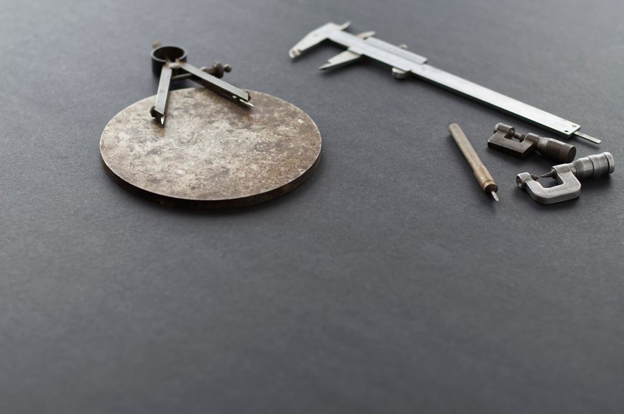
A tolerance means nothing until both sides agree how it is checked. ISO 1 sets 20 °C as the reference temperature, and the thermal example above shows why a warm stainless part reads large. Name the instrument for each tight feature, for example a plug gauge for an H7 bore or a micrometer for a turned diameter. Coordinate measurement and similar tests can be arranged on request through our production network, and the plan is agreed before the order.
FAQ
What is the standard CNC tolerance for stainless steel?
General CNC work holds about ±0.1 to ±0.13 mm (±0.005 in) without special effort. Marked features hold ±0.025 to ±0.05 mm, and ±0.01 mm needs a review of the feature, the grade and the finishing route.
Can you hold ±0.001 inch on 316 stainless steel?
Yes, on turned diameters and reamed or bored holes, which reach ±0.025 mm (±0.001 in) in the process chart. A flat face or a long feature may need a milling or grinding step, and the tolerance has to be met after any finishing.
Is a tighter tolerance always better?
No. A tighter tolerance adds operations, inspection and scrap risk, and the cost curve in the tier table rises steeply below ±0.025 mm. Tighten a feature only when it mates, seals, locates or carries load.
Does electropolishing change dimensions?
Yes. Electropolishing removes metal, 5 to 13 µm per surface in one aerospace specification, so a diameter shrinks by 10 to 25 µm. Put the finished size on the drawing and agree the removal with the finisher.
Should I machine 17-4PH before or after aging?
Either route works if the contraction is planned. Aging shrinks the part by 0.0004 to 0.0006 in/in at H900, so a tight feature is finished after aging, or machined to a size that allows for the change.
What to Send for a Tolerance Review
Send the drawing for custom CNC parts and we check which features can be held and at what cost, before you commit to a quote. These details help:
- The two or three features that carry the tight tolerances, with the fit or function of each
- The general tolerance class you want on everything else
- Material grade, heat treatment, surface finish and the inspection method you will use to accept the part
- Quantity, so the setup cost can be spread across the run
Conclusion
Hold ±0.1 mm as the default, tighten to ±0.025 to ±0.05 mm only on mating features, and reserve ±0.01 mm for the one or two features that need it. If you are looking for a new supplier of precision stainless steel CNC parts, send your drawing to Profab Machine and we will review each tolerance with you before we quote.