
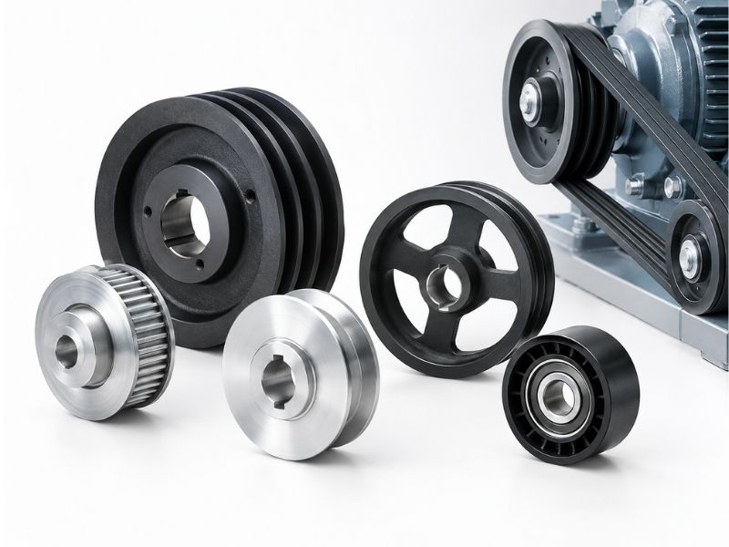
A pulley selection that starts with the wrong question — “what diameter do I need?” — usually produces a part that fits the drawing but fails the application. Diameter matters, but it’s determined by other constraints that come earlier in the decision chain. The medium type sets the groove geometry. The groove geometry and the cable or belt construction set the minimum diameter. Only then does the speed ratio determine where within that minimum the actual diameter lands.
Working through these decisions in the right order avoids the rework that comes from specifying groove geometry for a V-belt and then discovering the installation needs a wire rope sheave.
Step 1: Identify What's Running Through the Pulley
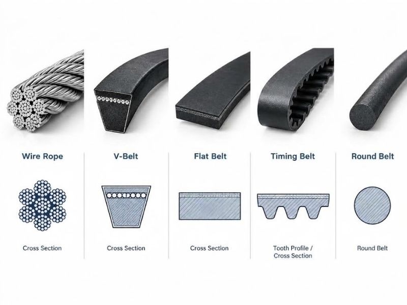
Every downstream selection depends on this. The transmission medium — what physically runs over or through the pulley — determines the groove profile, the diameter range, and the face width.
Wire rope and cable: Grooved sheaves with a rounded groove profile matching the cable OD. The groove radius should be 5 to 10% larger than the cable radius — large enough to allow the cable to seat fully without binding, small enough to support it on both flanks rather than letting it sit on the groove root. A groove that’s too wide lets the cable twist and wear unevenly; too narrow pinches and accelerates fatigue cracking in the wire strands.
V-belt: A trapezoidal groove with sidewall angle matched to the belt cross-section. Standard V-belt groove angles are 38°, 34°, and 32° depending on the belt profile (classical A/B/C/D, narrow SPZ/SPA/SPB/SPC). The belt rides on the groove flanks, not the groove root — the root clearance prevents the belt bottom from bottoming out as it wears. Classical and narrow V-belts of the same pitch width are frequently interchangeable on the same pulley provided the pitch and sidewall angle match.
Flat belt: A crown face or flat face pulley with no groove. Crowning provides passive belt tracking — the slight convex profile keeps the belt centred without flanges. Flat pulleys are used in light-duty drives, textile machinery, and conveyor tail ends.
Synchronous / timing belt: A toothed pulley with tooth pitch matched to the belt pitch. The pitch must be an exact match — a 5.08mm (XL) belt will not run on a 9.525mm (L) pulley, and there is no tolerance. Tooth profile also matters: trapezoidal teeth concentrate stress at the tooth root, limiting fatigue life at high torques. Curvilinear profiles such as GT2 and HTD distribute contact stress more evenly, which raises torque capacity by roughly 20–30% at equivalent pitch and diameter according to published belt manufacturer data. Specify curvilinear (GT or HTD series) for high-torque, high-cycle, or shock-loaded synchronous drives.
Round belt: A semicircular groove profile matching the belt cross-section OD. Used in light-duty drives, food processing (where round belt is common for its cleanability), and low-power torque transmission over irregular paths.
Step 2: Set the Minimum Pulley Diameter from Cable or Belt Constraints
Once you know the medium, the diameter is bounded from below. Running a cable or belt over a pulley that’s too small bends the medium beyond its fatigue limit and causes premature failure — not gradual wear but strand cracking or belt fatigue fracture.
For wire rope and cable: The minimum pulley diameter is set by the D/d ratio, where D is the pulley pitch diameter and d is the nominal rope diameter. The recommended ratio depends on the rope construction:
| Rope construction | Recommended minimum D/d ratio |
|---|---|
| 7×7 (rigid, low flexibility) | 40× |
| 7×19 (general purpose) | 25× |
| 7×37 or 7×49 (high flexibility) | 15× |
A 10mm diameter 7×19 wire rope therefore requires a minimum sheave pitch diameter of 250mm. Running it over a 100mm sheave accelerates strand fatigue and reduces rope life to a fraction of the rated cycles. The D/d ratios above represent starting points for maximum rope life — if space constraints force a smaller diameter, service life shortens proportionally and inspection intervals must be reduced accordingly.
For V-belts: Belt manufacturers publish minimum pulley diameter recommendations by belt profile. Classical A-belt: 75mm minimum. Classical B-belt: 100mm. Narrow SPZ: 63mm minimum. Below these diameters, belt sidewall cracking and early delamination are predictable within a few thousand hours.
For timing belts: Minimum tooth count on the small pulley governs. Below 12 to 15 teeth in mesh (depending on pitch), the per-tooth load exceeds what the tooth shear cross-section can carry reliably. Minimum tooth count on the driven pulley is typically 10 to 12 for standard trapezoidal profiles, 15 or more for high-torque applications.
After you’ve confirmed minimum diameter from the medium constraint, speed ratio sets the actual diameters. Speed ratio = driven pulley diameter ÷ drive pulley diameter. A 4:1 reduction uses a drive pulley at the minimum permissible diameter and a driven pulley four times larger. If the minimum diameter already produces a driven pulley that exceeds the space envelope, the problem is centre distance or transmission type, not pulley selection.
Step 3: Confirm Groove Profile and Face Width
Groove profile must match the transmission medium exactly. But within that constraint, there are decisions that affect performance.
Number of grooves: A multi-groove pulley runs multiple belt strands in parallel, increasing the torque capacity without increasing the pulley diameter. Specify a multi-groove configuration when the required torque exceeds what a single belt strand can carry at the available pulley size.
Groove angle for V-belts: Standard groove angles are specified in ISO 4183 and BS 3790. The groove sidewall angle must match the belt’s included angle — a mismatch of even a few degrees changes the contact arc and shifts the belt’s running position, generating heat and accelerating sidewall wear. When replacing pulleys, verify the groove angle against the belt manufacturer’s specification for the belt series, not just the nominal profile letter.
Face width for flat and round belt pulleys: Must accommodate the belt width with clearance on each side. A face that’s too narrow causes the belt to ride off the edge. Crowning height on flat pulleys is typically 0.5% of face width as a rule of thumb, sufficient to keep a flexible flat belt tracking without a flange.
Flanges on timing belt pulleys: Flanges prevent the belt from walking off the pulley under misalignment. The smaller pulley in a two-pulley drive should always be flanged. When shaft misalignment is a concern or more than two pulleys are in the system, flange both pulleys.
Step 4: Specify Bearing or Bushing and Bore-to-Shaft Fit
The bearing or bushing inside the pulley determines friction, maintenance interval, load capacity, and whether the pulley can be serviced in the field.
Plain bore (no bearing): The pulley bore runs directly on the shaft or on a separate plain bushing. Suitable for slow-speed, low-load applications where the bore surface has adequate hardness. Requires lubrication at the bore interface. Common in simple rope sheaves, guide pulleys, and low-RPM material handling.
Ball bearing: The most common configuration for driven and drive pulleys in industrial applications. Sealed bearings block dust and moisture and require no field lubrication — specify sealed bearings for outdoor, dusty, or wet environments. Open bearings allow relubrication and are preferred where the operating temperature or load makes bearing replacement more frequent than the bearing’s rated life.
Double-row or self-aligning bearing: For applications where shaft deflection under load or slight misalignment between bearing housings is expected. Self-aligning spherical bearings compensate for up to 3° of shaft misalignment. Required in long conveyor pulleys where shaft deflection under belt tension is predictable.
Bore fit: The bore diameter must match the shaft diameter with the correct fit class. For keyed connections, H7/k6 or H7/n6 interference fit is standard — H7/k6 for normal torque, H7/n6 for heavy or reversing loads. A loose H7/g6 fit is acceptable for pulleys that must slide axially. An undersized bore creates stress risers at the shaft contact surface; an oversized bore allows micro-slip and fretting. Confirm the bore tolerance against the shaft tolerance class before ordering.
Keyway: When the pulley must transmit torque and not slip, a keyway in the bore engages a matching key on the shaft. Specify the key standard (DIN 6885, JIS B 1301, or inch Woodruff) to match the shaft. Set screws alone are not adequate for torque transmission in continuous-duty drives.
Taper lock (QD) hub: A split taper bushing clamps to the shaft when the bolts are tightened. Allows pulley removal without shaft disassembly — critical in applications where downtime for pulley replacement must be minimised. The taper lock hub is a separate component from the pulley and must be specified in the matching bore size and taper series.
Step 5: Match Material Grade to the Operating Environment
Material selection determines whether a pulley lasts its rated cycle life or requires replacement at a fraction of it due to corrosion, wear, or weight constraints.
Cast iron: The standard material for industrial V-belt and synchronous belt pulleys. High damping capacity reduces vibration transmission. Good machinability and weldability. Not suitable for wet outdoor or chemical environments — surface rust develops and eventually compromises the groove surface finish, which accelerates belt wear.
Carbon steel: Higher strength than cast iron at equivalent section size. Used where wall section must be thinner than cast iron allows, or where weld-in construction is required. Subject to the same corrosion limitations as cast iron without a protective coating.
Stainless steel (304 / 316L): Required for food processing, marine, pharmaceutical, and chemical plant pulley applications where the pulley sees washdown, seawater, or process fluid contact. 316L adds molybdenum for superior chloride resistance. Stainless pulleys maintain groove surface finish across repeated cleaning cycles that would corrode a carbon steel pulley within months. Heavier than aluminium at equivalent size but significantly more corrosion-resistant.
Aluminium: Light weight with adequate strength for most drive pulley applications at moderate loads. Anodised aluminium provides surface hardness for the groove contact surface. Common in automotive, aerospace, and weight-critical machinery. Not suitable for highly abrasive environments — aluminium groove surfaces wear faster than steel under abrasive particle contact.
Nylon and engineering plastics: For light-duty guide pulleys, idlers, and cable deflection pulleys where low weight, low noise, and no requirement for lubrication are priorities. Not suitable for high-torque power transmission drives. Plastic pulleys are standard in garage door hardware, medical equipment, and light conveyor systems.
⚠️ Note: If your pulley runs in a food processing or pharmaceutical environment and sees any CIP cleaning, specify 316L stainless with a smooth groove surface finish. Cast iron and carbon steel pulleys corrode at the groove root within the first cleaning season, producing rust particles that contaminate the product zone and accelerate belt or rope wear simultaneously.
Step 6: Specify Surface Finish and Mounting Configuration
Surface finish on the groove: The groove surface finish affects belt and cable wear rate directly. A rough groove surface (Ra > 3.2 µm) abrades the belt contact surface and generates heat under load. A ground or turned groove at Ra 1.6 µm or better is standard for precision belt drives and wire rope sheaves. Electropolished grooves on stainless pulleys reduce the bacterial adhesion surface for food and pharmaceutical applications.
Mounting configuration: How the pulley attaches to the shaft or structure determines service access and alignment.
Fixed bore pulleys are pressed or keyed onto the shaft and require shaft removal or pulley withdrawal to service the belt. Use where maintenance is infrequent and shaft access is easy.
Split pulleys have a two-piece body that can be assembled around the shaft without shaft removal. Useful in awkward installation positions where pulling the shaft is difficult.
Idler pulleys mount on a fixed pin or bracket rather than a driven shaft. They guide belt path, maintain tension, or change belt direction without transmitting power. Idlers typically use sealed ball bearings and do not require a keyway.
Flange-mount pulleys attach to a structural face plate via bolted flange rather than to a shaft through the bore. Common in hoisting and crane sheave blocks.
Putting It Together
The right sequence for pulley selection:
- Confirm the transmission medium (wire rope, V-belt, timing belt, flat, round)
- Determine minimum pulley diameter from the D/d ratio or belt minimum diameter table
- Set speed ratio and confirm resulting diameters fit the installation envelope
- Specify groove profile, number of grooves, face width, and flanges to match the medium
- Select bearing or bushing type, bore diameter, fit class, and keyway or taper lock configuration
- Choose material grade to match the operating environment
- Specify surface finish on the groove face and the mounting configuration
Skipping step 1 or 2 is where most wrong pulley orders originate. A rope sheave groove will not run a timing belt. A timing belt pulley at the wrong pitch will not mesh with the belt regardless of how close the diameter is. Getting those two decisions right before touching a catalogue makes the rest of the selection straightforward.
Profab Machine manufactures stainless steel pulleys in 304 and 316L for food processing, marine, and chemical plant applications, in V-groove, round groove, and flat face configurations, with custom bore, keyway, and groove profiles to drawing.