
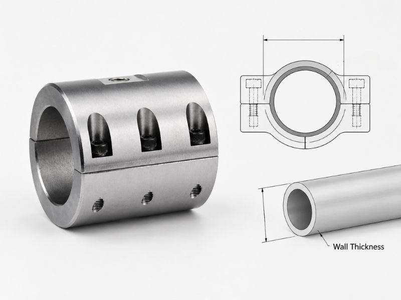
Tube clamp selection looks straightforward until you order the wrong size. The most common cause isn't measuring the wrong diameter: it's confusing tubing OD with pipe nominal size, or ignoring wall thickness and discovering the clamp either can't close fully or deforms the tube at installation torque.
This guide walks through both dimensions in the order they matter for clamp selection.
Step 1: Measure Tube OD, Not Pipe Nominal Size
Tubing and pipe use different sizing conventions. Tubing is specified by actual outer diameter. Pipe is specified by nominal pipe size (NPS), which doesn't correspond to any actual dimension on the pipe itself — a 1-inch NPS pipe has an OD of 33.4mm, not 25.4mm.
If you're working with tube, measure the actual outside diameter with calipers. If you have a drawing, use the OD dimension stated, not the nominal size. Ordering a clamp based on nominal pipe size for a tubing application is one of the most common reasons clamps arrive and don't fit. For the full breakdown of why NPS and tube OD diverge, see Tube OD vs Nominal Pipe Size.
| Tube OD (mm) | Common wall thickness range |
|---|---|
| 6 | 0.5 – 1.0 mm |
| 8 | 0.5 – 1.5 mm |
| 10 | 0.5 – 2.0 mm |
| 12 | 0.5 – 2.0 mm |
| 16 | 0.5 – 2.0 mm |
| 20 | 1.0 – 3.0 mm |
| 25 | 1.0 – 3.0 mm |
| 38 | 1.5 – 3.0 mm |
| 51 | 1.5 – 3.0 mm |
A stainless steel OD tube clamp is sized to the tube's actual OD. The clamp's working range must bracket the tube OD you've measured, with the tube OD ideally falling near the midpoint of the range rather than at either extreme.
Step 2: Understand What Wall Thickness Does to Clamp Selection
Wall thickness doesn't change which clamp size you order. The clamp still attaches to the tube OD. What wall thickness determines is how much clamping force the tube wall can withstand before deforming, and whether a clamp with a rigid liner can close correctly around the tube.
Thin-wall tube (under 1.0mm wall): A thin-wall tube compresses under excessive bolt torque. The tube wall deforms inward rather than the joint holding. On process piping or instrumentation tubing with walls of 0.5mm to 0.7mm, a rigid stainless liner inside the clamp can apply concentrated stress at the liner edges rather than distributing force around the full tube circumference. For thin-wall tube, specify clamps with elastomeric liners that distribute load across a wider arc, or verify the clamp body design distributes force evenly before installation.
Standard wall tube (1.0mm – 2.0mm): The most common range. Most OD tube clamps are designed for this wall thickness range. The clamp body closes around the tube and the bolt applies uniform circumferential force. No special consideration required beyond matching OD and confirming material compatibility.
Heavy wall tube (above 2.0mm): Wall thickness reduces the effective space inside the clamp. A clamp designed for a 25mm OD tube with 1.0mm wall accommodates 23mm ID. The same clamp on a 25mm OD tube with 3.0mm wall is still correct for the OD, but the tube is structurally stiffer. Heavy wall tubes don't need liner protection from clamp force, and the higher rigidity means they resist deformation even at higher installation torques.
Step 3: Identify the Clamp Type for Your Application
OD tube clamps differ in how they apply force and how they mount. The tube OD and wall thickness narrow the material choice; the application determines the clamp type.
Single-bolt OD clamp: One bolt draws the two clamp halves together around the tube. Simple, fast to install, and suitable for most process tube support applications. The single bolt creates slightly asymmetric loading: one side of the tube sees more force than the other as the bolt side closes first. For thin-wall tubes at the edge of acceptable wall thickness, a two-bolt design is more appropriate.
Two-bolt OD clamp: Two bolts, one on each side, close the clamp symmetrically. Force distribution around the tube circumference is more even. Preferred for thin-wall tubes, for clamps that must align tubes precisely, and for applications with vibration where one bolt loosening would cause the clamp to rotate.
Back-to-back or multi-tube clamp: Multiple tubes clamped in a stacked or side-by-side configuration using a single mounting bolt. Used for routing parallel tube bundles in panel installations, instrumentation systems, and hydraulic power units. Each tube position has its own insert or liner sized to the individual tube OD.
Cushioned clamp (with elastomeric liner): A rubber or EPDM liner sits between the stainless body and the tube OD. The liner absorbs vibration transmitted through the tube to the mounting surface, prevents galvanic contact between dissimilar metals in some assemblies, and distributes force around thin-wall tube without creating stress concentrations at the body edges. Specify for pneumatic and hydraulic lines subject to pressure pulsation, and for food-processing environments where tube vibration from pump cycles transmits to the mounting structure.
Step 4: Match Material Grade to the Environment
The clamp body, liner, and hardware all contact the environment around the tube. Each has a material requirement.
304 stainless body: For indoor, dry, or low-humidity installations. General industrial, HVAC, pneumatic tube routing, and instrumentation in non-corrosive environments.
316L stainless body: For marine environments, coastal installations, food-processing lines, chemical plants, and anywhere the clamp sees salt spray, washdown chemicals, or sanitizers. The molybdenum content in 316L raises the threshold for chloride pitting at the clamp screw threads and body edges, which are the surfaces most vulnerable to crevice corrosion. Clamp bolt hardware should also be 316L. A 304 bolt has lower chloride resistance than a 316L body on its own, not primarily from galvanic coupling between the two grades (304 and 316 sit close enough in the galvanic series that coupling risk is low), but because the bolt itself pits and corrodes faster in the same wet, chloride-bearing environment the body is rated to handle.
Liner material compatibility: The elastomeric liner is the component most affected by the chemical environment. EPDM handles water, steam, dilute acids, and mild alkalis. NBR handles petroleum-based oils and hydraulic fluids. Silicone handles temperature extremes from –60°C to +200°C with moderate chemical resistance. In CIP applications using NaOH at 0.5–2% concentration at 60–80°C, EPDM is the appropriate specification. NBR rates only moderate on chemical resistance against sodium hydroxide, well below EPDM's excellent rating, and degrades faster in this chemistry.
Step 5: Confirm Mounting and Installation Clearance
A clamp that fits the tube OD and is rated for the environment still needs to physically install in the available space.
Back clearance: The tube clamp mounts to a surface — panel, strut, or structure — with a bolt or channel nut. The clamp body depth plus the tube radius determines how far the tube centerline sits from the mounting surface. For tube bundles in panel installations, this sets the minimum spacing between mounting rails. Verify the tube centerline height against the panel layout before finalizing the clamp model.
Axial spacing: Tube clamps support tubes at defined intervals to prevent vibration-induced fatigue. The supported span depends on tube OD, wall thickness, and the tube's internal pressure or weight loading. Thin-wall, large-OD tubes need closer spacing than thick-wall, small-OD tubes. For process piping, manufacturer span tables or piping support standards define maximum unsupported length.
Installation torque: Stainless steel fasteners on stainless clamp bodies gall under aggressive torque. Apply anti-seize to the bolt thread before installation. Tighten to the clamp manufacturer's specified torque, which is lower than you might expect for a stainless-to-stainless assembly, and stop before the bolt shows resistance increase from galling. Torquing past the specified value on thin-wall tube will deform the tube before the bolt breaks.
A One-Page Checklist
Before ordering, confirm these five things:
- Tube OD measured or confirmed from the drawing — not nominal pipe size
- Wall thickness known — determines liner type and acceptable installation torque
- Clamp type selected — single bolt, two bolt, cushioned, or multi-tube
- Material grade matched to environment — 304 for dry, 316L for wet or chemical
- Liner material confirmed against the process chemistry — EPDM, NBR, or silicone
If the application involves tube OD outside standard sizes, thin-wall tube under 0.8mm, or chemical environments that aren't clearly covered by standard liner options, confirm the clamp specification with the supplier before the order rather than after installation.
Conclusion
Tube clamp selection comes down to five checks in order: measure the actual tube OD instead of nominal pipe size, confirm wall thickness for liner and torque limits, pick the clamp type the application needs, match the body and liner material to the environment, and verify mounting clearance before ordering.
Profab Machine manufactures stainless steel OD tube clamps for food, pharmaceutical, and marine applications.