- By Profab /
- May 15, 2026
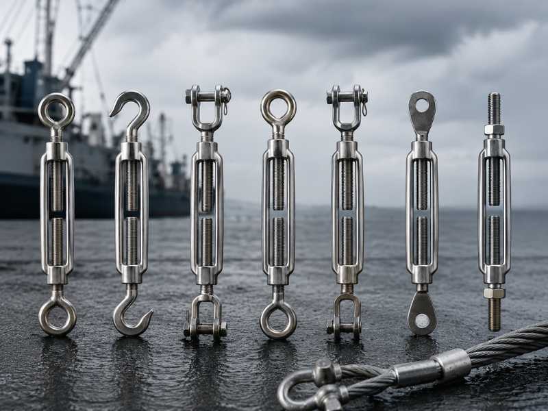
Table of Contents
A turnbuckle is one of the most widely used tensioning devices in rigging, marine hardware, and structural applications, yet it is also one of the most frequently under-specified. End fitting type, body style, thread diameter, take-up length, and material all affect whether a turnbuckle is the right component for a given application. Choosing by size alone, without considering connection method or operating environment, leads to assemblies that are either over-stressed or incompatible at the connection points.
This guide covers the complete selection picture: how turnbuckles work, the five end-fitting types and when each applies, how to read size specifications, installation and tightening procedure, and why material grade matters more than most product descriptions acknowledge.
Five End-Fitting Types and When to Use Each
End fitting selection is driven by what the turnbuckle must connect to and whether the connection is permanent, semi-permanent, or temporary.
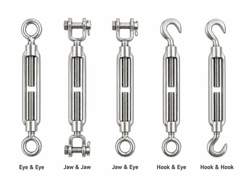
Eye and Eye
Both ends carry a closed loop (the eye). The eye connects via a shackle or pin passed through the loop. Eye-and-eye is the most versatile configuration because it pairs with shackles, pad eyes, eye bolts, and chain links without modification. It is used for both permanent and semi-permanent assemblies. Since the eye is a closed fitting, there is no risk of the connection opening under load reversal or vibration.
Eye-and-eye is the most common configuration in marine rigging, structural cable systems, and industrial tensioning assemblies.
Jaw and Jaw
Both ends carry a clevis jaw: a U-shaped fork with a through-bolt or pin. The jaw fits over a pin, ear, or clevis bracket and is secured by inserting the bolt and tightening the nut. Jaw-and-jaw provides positive, non-rotational retention at both ends and is the preferred configuration where vibration could unseat a less secure fitting.
This configuration is used in actuator linkages, industrial machinery, and structural connections where the attachment point is a pin or bracket rather than an eye or shackle.
Jaw and Eye
One jaw end, one eye end. This hybrid covers the common case where one anchor point is a pin or bracket (jaw) and the other is an eye bolt or shackle (eye). It avoids forcing a mismatched connection type at either end.
Hook and Eye
A hook at one end, an eye at the other. Hooks allow rapid connection and disconnection without tools, which is useful in temporary rigging setups, theatrical rigging, and applications where the assembly is frequently reconfigured.
Hooks should always be secured with a safety latch or moused with seizing wire when used in load-bearing applications. They are not appropriate for overhead lifting unless specifically rated for that use by the manufacturer.
Hook and Hook
Both ends carry hooks. Hook-and-hook is appropriate only for temporary, non-critical connections where quick attachment and release are the primary requirement. For any application where unexpected tension release could cause injury or damage, hook configurations are disqualifying.
Open Body vs. Closed Body
Beyond end fitting type, turnbuckle bodies come in two structural configurations.
Open body. The central frame exposes the threaded rods on both sides. This allows visual inspection of thread engagement at a glance, and the open structure makes lubrication of the threads straightforward. Open-body turnbuckles are the standard for industrial rigging, marine hardware, and structural applications where thread inspection is required as part of routine maintenance.
Closed body (bottle screw). A tubular housing encloses the threads. Closed-body designs are common in architectural and decorative cable systems where the threaded mechanism is not meant to be visible. The enclosed housing provides some protection against contamination in outdoor installations. Inspection requires disassembly or the use of inspection holes built into the housing on compliant hardware.
For most functional applications, open-body is preferred because it allows direct thread engagement verification, which is a safety-critical check.
How a Turnbuckle Works
A turnbuckle achieves tension adjustment through opposing thread directions on a single body. One end fitting carries a right-hand thread; the other carries a left-hand thread. Both thread into the central body.
When the body rotates, both end fittings draw inward simultaneously, shortening the assembly and increasing tension on whatever is attached. Rotating in the opposite direction extends both fittings and releases tension. Because the threads are opposed, the body can adjust tension without rotating the cables, wires, or rods attached to it. The load stays in line; only the body turns.
The practical result is a compact, field-adjustable tensioning device that can generate several tonnes of tension on large rigging hardware with no special tooling, and that can be re-adjusted without disconnecting the assembly.
Three dimensions define how much adjustment is available: the thread diameter (which determines load capacity), the body length, and the take-up, which is the total linear travel from full extension to full closure. Standard take-up lengths are 6 inches, 12 inches, 18 inches, and 24 inches. Longer take-up gives more adjustment range but results in a longer assembled device.
What Are Turnbuckles Used For
Turnbuckles appear in any application that requires controlled, adjustable straight-line tension. Common uses include:
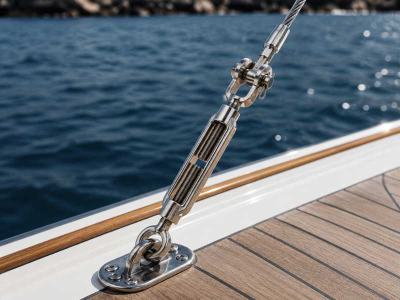
Marine and sailing. Mast stays, shrouds, and forestays on sailboats require precise and re-adjustable tension. Turnbuckles, often called rigging screws in European markets, are standard hardware for wire rope standing rigging. Deck lifelines, boarding ladders, and cargo lashing on commercial vessels use them for the same reason: tension that can be verified and adjusted without replacing the line.
Structural and architectural. Cable bracing in buildings uses turnbuckles to tension diagonal rods or wire rope members, keeping structural frames plumb during and after erection. Architectural cable railings, facade systems, and tensioned canopy structures use turnbuckles to maintain aesthetic uniformity and accommodate the seasonal movement that thermal expansion and contraction produce.
Industrial rigging. Turnbuckles extend the effective length of rigging assemblies and allow load balance adjustment across multiple lift points. In any multi-leg lift where sling lengths do not match perfectly, a turnbuckle in one leg allows fine adjustment without replacing hardware.
Fencing and agriculture. Gate bracing, fence wire tensioning, and livestock enclosure wires use light-duty turnbuckles to maintain wire tension over spans where wire would otherwise sag.
Food and pharmaceutical processing. Conveyor frames, tension members in sanitary equipment, and cable guide systems in food-grade environments specify stainless steel turnbuckles for corrosion resistance and compliance with cleaning cycle requirements.
Turnbuckle Sizes: How to Read the Specification
Turnbuckles are specified by two primary dimensions: thread diameter and take-up length, expressed as a combined designation such as 1/4 x 4″ or M10 x 150mm.
Thread diameter is the diameter of the threaded shank on each end fitting. Larger thread diameter means higher working load limit (WLL). For a given end-fitting configuration and material, WLL scales with the cross-sectional area of the threaded section.
Take-up is the total linear travel available, not the body length. A 1/4″ x 4″ turnbuckle has 4 inches of take-up: when fully extended, the end fittings are 4 inches further apart than when fully closed.
A practical reference for stainless steel open-body turnbuckles (jaw and eye, 316 stainless):
| Thread Diameter | Take-Up | Approx. WLL |
|---|---|---|
| 1/4" (M6) | 4" (100mm) | 170 kg / 375 lb |
| 5/16" (M8) | 6" (150mm) | 300 kg / 660 lb |
| 3/8" (M10) | 6" (150mm) | 500 kg / 1,100 lb |
| 1/2" (M12) | 6" (150mm) | 800 kg / 1,760 lb |
| 5/8" (M16) | 12" (300mm) | 1,400 kg / 3,080 lb |
| 3/4" (M20) | 12" (300mm) | 2,100 kg / 4,600 lb |
WLL figures are indicative for 316 stainless open-body turnbuckles. Always confirm against the manufacturer’s rated specification for the specific product, end-fitting type, and applicable standard (ASME B30.26, EN 1677, BS 4429, or equivalent).
The thread diameter must match the mating hardware. A 3/8″ turnbuckle body will not correctly engage a 5/16″ eye bolt, even if the difference seems minor. Thread pitch as well as diameter must match across the assembly.
Material: Where Stainless Steel Is the Right Specification
Turnbuckles are most commonly available in two material categories: hot-dip galvanized carbon steel and stainless steel (typically 304 or 316).
Galvanized carbon steel is cost-effective and carries high load ratings for its size. It is appropriate for dry or indoor environments and applications where corrosion exposure is limited. In marine, coastal, or food-processing environments, galvanized turnbuckles will corrode at the zinc coating edges, at thread roots, and at any surface where the coating is abraded during installation. Once the zinc layer is compromised, corrosion progresses rapidly.
Stainless steel turnbuckles are the correct specification for:
Marine and saltwater environments. The passive chromium oxide layer on 316 stainless provides active corrosion resistance that galvanized coating cannot replicate in continuous saltwater or salt-air exposure. For standing rigging on vessels, deck hardware, and lifeline systems, 316 stainless is the baseline material. 304 is suitable for protected offshore environments; exposed coastal or offshore applications specify 316.
Food processing and sanitary applications. Stainless is the only material compatible with chlorinated cleaning cycles. 316L is preferred where welding is involved; 316 is standard for machined and assembled components.
Architectural cable systems. Stainless provides the long-term appearance stability that architectural applications require. Galvanized hardware stains surrounding surfaces as the zinc weathers.
Chemical and industrial environments. Where cleaning agents, process chemicals, or high humidity are present, stainless provides longer service life without the surface degradation that affects galvanized hardware.
Within stainless, 316 (EN 1.4401) is preferred over 304 (EN 1.4301) wherever chloride exposure is possible. The molybdenum content in 316 stabilizes the passive layer against chloride-induced pitting, which is the dominant corrosion mode in marine and food-processing environments. For applications confirmed to be non-chloride and non-marine, 304 is a cost-effective alternative.
How to Use a Turnbuckle: Installation Steps
Step 1. Extend the end fittings fully before installation. Unscrew both end fittings until they are at maximum extension. This ensures the full take-up range is available for tensioning after attachment.
Step 2. Connect the end fittings to the anchor points. For eye ends: pass a shackle pin through the eye and secure to the anchor point. Close and pin the shackle. For jaw ends: open the jaw bolt, seat the jaw over the pin or fitting, reinsert the bolt, and tighten the nut fully. For hook ends: engage the hook and secure with a mousing wire or safety latch.
Step 3. Set the initial position near mid-travel. Before tensioning, adjust both end fittings so the body sits near the middle of its available take-up range. This reserves adjustment capacity in both directions and avoids starting the tensioning process at a position where one end has minimal thread engagement.
Step 4. Tension by rotating the body. Rotate the body by hand to begin drawing the end fittings inward. In open-body turnbuckles, watch the thread stubs through the body to verify both sides are engaging evenly.
How to Tighten a Turnbuckle Correctly
Turnbuckles can be tightened by hand, with a bar through the body, or with a wrench on a wrench flat if the body provides one. Each method has appropriate applications and limits.
Hand tightening is sufficient for light-duty applications and initial positioning. For anything with a load requirement, hand tension alone is not reliable.
Bar through the body (a screwdriver or rod passed through the open frame of an open-body turnbuckle) gives mechanical advantage for final tightening. Use a smooth rod sized appropriately for the opening. Do not use a pry bar or pipe that could damage the body under load.
Wrench on the end fittings is not appropriate. End fitting nuts are retention hardware, not tightening surfaces. Using them to drive rotation will deform threads.
The most critical tightening checkpoint is thread engagement. Both end fittings must be threaded into the body by a minimum distance equal to 1.5 times the thread diameter. On open-body turnbuckles, the thread should be visible passing the inspection hole or window machined into the body. Running an end fitting nearly out of the body to reach a connection point, then tensioning, is a common failure mode and a serious safety hazard.
Once final tension is achieved, secure the body against unintentional back-rotation. Methods include:
Jam nuts on each end fitting, tightened against the body end face to lock the threaded position. Seizing wire (mousing wire) passed through the body and end fittings in a figure-eight pattern. This is the standard for marine rigging hardware and applications subject to vibration. Locking pins through the body on some proprietary designs.
For turnbuckles in dynamic applications, vibration during service will cause the body to back off over time without positive locking. Seizing wire is the most reliable field solution for marine and rigging applications.
Send Inquiry Now
Related Resource
Types of Turnbuckles: End Fittings, Sizes, and How to Use Them