
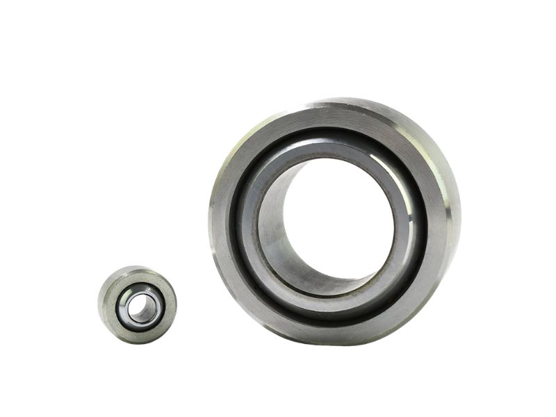
Bearing catalogues size a spherical bearing under combined radial and axial load by converting the axial force into an equivalent radial load, so that is the first step. Then check the resulting contact pressure against the liner limit, and confirm sliding speed and temperature. The GE-type catalogues we checked publish no separate axial rating, so the whole selection runs on the equivalent radial load.
| Step | What you calculate | What you check it against |
|---|---|---|
| 1. Load direction | Radial load Fr, axial load Fa, ratio Fa/Fr | Mostly radial, or a different bearing type |
| 2. Equivalent load | P = Fr multiplied by a factor for Fa/Fr | The range of Fa/Fr the factor covers |
| 3. Contact pressure | p = 100 × P / C (N/mm²) | 100, 60 or 40 N/mm² depending on load pattern |
| 4. Speed and temperature | Mean sliding speed v, operating temperature | The catalogue's speed and temperature limits |
| 5. Liner and ring material | Maintenance access, environment, ring material | A rating reviewed for your actual material |
Start With the Load Direction
A purely radial load needs no conversion, and a published bearing catalogue lets you use it directly. Once an axial component is present, the bearing is sized on an equivalent load instead, so the first job is to find out whether Fa is real.
Axial load often is not stated on the drawing, so estimate it from the geometry before assuming it is zero. A typical catalogue example is a shock-absorber attachment on an off-highway vehicle, carrying 0.7 kN of axial load alongside 7 kN of radial load.
The published factors stop early. The published factors stop at a limited Fa/Fr: the curve for GE..C-type bearings ends early, and another maker's table ends at 0.5. Past that range no catalogue factor exists, so a higher Fa/Fr is outside the published method and needs case-by-case review. A published catalogue also points a combined load with a large axial share (an Fa/Fr above about 2) to angular contact or thrust spherical bearings.
Convert Axial Load to an Equivalent Radial Load
The equivalent radial load P is the single number you size the bearing on. One method, from a published selection guide, adds the axial load to the radial load with a factor: P = Fr + Y × Fa, where Y depends on Fa/Fr.
The other common method multiplies instead: P = y × Fr, with y read from a curve. Only one value is printed as a number, 1.4 at an Fa/Fr of 0.1, so the table shows that value and no others for the curve.
| Fa/Fr up to | 0.1 | 0.2 | 0.3 | 0.4 | 0.5 |
|---|---|---|---|---|---|
| Additive method: factor Y | 0.8 | 1 | 1.5 | 2.5 | 3 |
| Additive method: P as a multiple of Fr (1 + Y × Fa/Fr) | 1.08 | 1.20 | 1.45 | 2.00 | 2.50 |
| Multiplier method: factor y for GE..C (printed value only) | 1.4 | not printed | not printed | not printed | not printed |
The multiples in the second row are our arithmetic on the published factors. The two methods are not interchangeable, because each rests on its own maker's rating definition and bearing type: at an Fa/Fr of 0.1 the additive multiple is 1.08 while the multiplier is 1.4. One catalogue also states that load ratings from different manufacturers cannot be compared.
The additive table is published for that maker's own spherical plain bearings, with an SB model in its worked example, and names no PTFE-lined type. Take the method, the ratings and the K factor from the same catalogue, and do not apply one maker's factors to another maker's bearing, including a Profab part.
Check Contact Pressure Against the Liner Limit
Contact pressure is the first check of whether the liner can last, and the allowable value depends on how the load behaves. For a steel and PTFE sintered bronze bearing, the specific bearing load is p = K × P / C. Here K is 100 N/mm², P and C are in kN, and C is the dynamic load rating.
K and C are defined together, so use this formula only with ratings from the same catalogue. The cap on p is 100 N/mm² for a load that always acts in one direction. If the load alternates or pulses at up to 0.5 Hz the cap falls to 60 N/mm², and between 0.5 and 5 Hz it falls again to 40 N/mm².
These limits qualify the point for the catalogue's life equation, Gh = b1 × b2 × 1400 / (p1.3 × v), in hours. Here b1 is 1, 0.4 or 0.2 for the three load patterns above, b2 is a temperature factor given as a curve, and v is the sliding speed. Passing the pressure limit does not by itself show adequate life.
As a first screen, the guideline for this sliding system is a ratio C/P of about 1.6 or higher. The static check follows the same logic: the total load must not exceed the static rating C0.
Worked Example: GE20C Under Combined Load
Take the GE20C, the 20 mm bore size in the GEC series: 35 mm outside diameter, 16 mm inner ring width, 12 mm outer ring width and a 9 degree tilt angle. Profab's series tables do not publish load ratings, because the rating depends on the ring material and liner.
To show the method, we use values a catalogue publishes for the same envelope size: C = 31.5 kN, C0 = 78 kN and a sphere diameter of 29 mm. The operating case is that catalogue's own example. It has Fr = 7 kN and Fa = 0.7 kN. The joint oscillates through a half angle of 8 degrees at 15 oscillations per minute, with a load frequency of 2 to 5 Hz and a temperature up to 75 °C.
| Step | Calculation | Result |
|---|---|---|
| Load ratio | Fa / Fr = 0.7 / 7 | 0.1 |
| Equivalent load | P = y × Fr = 1.4 × 7 kN | 9.8 kN |
| Contact pressure | p = 100 × 9.8 / 31.5 | 31.1 N/mm² |
| Same load without Fa | p = 100 × 7 / 31.5 | 22.2 N/mm² |
| Pressure limit | 40 N/mm² band, because the load frequency is 2 to 5 Hz | Within the limit, 22 percent below it |
| Sliding speed | v = 5.82 × 10⁻⁷ × 29 × 8 × 15 | 0.0020 m/s |
| Life | Gh = b1 × b2 × 1400 / (p1.3 × v) = 0.2 × 1 × 1400 / (31.11.3 × 0.0020) | about 1,600 h |
| Rating margin | C / P = 31.5 / 9.8 | 3.2 |
| Static margin | C0 / P0 = 78 / 9.8 (P0 uses the same factor y) | 8.0 |
An axial load of only a tenth of the radial load raised the contact pressure by 40 percent. That 40 percent is the factor at an Fa/Fr of 0.1, and the factor rises steeply as the ratio grows.
The pressure and C/P margins look comfortable, but the life is not. Against that catalogue's requirement of 100,000 km at 65 km/h, which is about 1,540 hours, 1,600 hours is a thin pass. The life check decides this design, not the pressure check. Here b1 is 0.2 for the 2 to 5 Hz load frequency and b2 is 1, because the temperature stays below 80 °C.
These are published catalogue values used to show the method. They are not load ratings for any Profab part.
Check Sliding Speed and Temperature
For an oscillating joint, the catalogue gives the mean sliding speed as v = 5.82 × 10⁻⁷ × dm × β × f, in metres per second. Here dm is the sphere diameter in mm, β is the half oscillation angle in degrees (90 for continuous rotation), and f is the number of oscillations or revolutions per minute.
Temperature limits the liner too. The catalogue gives a permitted temperature range for steel and PTFE sintered bronze bearings and reduces carrying capacity above 80 °C. A hot application therefore needs its rating reduced before it is compared with P.
Pick the Liner and Ring Material
Choose the liner for maintenance access first. Guideline friction values overlap between steel on PTFE sintered bronze (0.05 to 0.25) and steel on steel (0.08 to 0.20), and a PTFE fabric liner is lower at 0.02 to 0.15. A PTFE liner earns its place where nobody can grease the joint regularly.
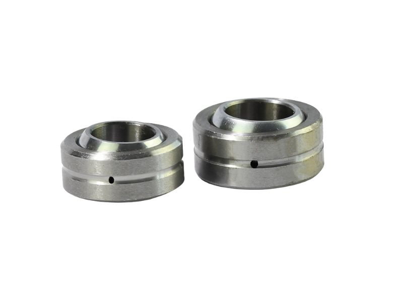
The GEC series is Profab's metric radial bearing with a self-lubricating PTFE-lined race, in bores from 4 to 30 mm. Its published tilt angles run from 16 degrees (GE4C) to 6 degrees (GE30C), and the wider GEG series lists 16 to 21 degrees.
Ring material changes the rating. A standard GE..C-type catalogue bearing has a hard-chromium-plated steel inner ring, so its published rating cannot be carried over to a stainless ring. A stainless ring is usually softer than a chromium-plated or hardened ring, so it can carry less load and, against a stainless mating part, it adds a galling risk. Stainless options for the GEC series are confirmed at quotation, against your drawing and application.
The ring grade also decides how much load the bearing can carry, which is covered in 17-4PH versus 316.
For joints nobody can grease, read about self-lubricating liners, including the pV ceiling a PTFE liner has.
What to Send for a Load Review
Send the following with your drawing and we review it against your application and tell you which series, liner and ring material fit:
- Radial load and its direction, and whether it is steady, alternating or shock
- Axial load, its direction, and where it comes from
- Oscillation angle and frequency, or rotating speed
- Bore, outside diameter and ring width envelope
- Operating temperature and environment (washdown, salt spray, chemicals)
- Grease access, quantity, and any liner or ring material preference
Profab's spherical bearing range (COM, COM-T, GEC, SLB, WPB and YPB series) offers metal-to-metal, PTFE-lined and injection-molded sliding systems, and we set the liner and ring material to suit your drawing before we quote.
Conclusion
Size a spherical bearing for combined load on the equivalent radial load, using one catalogue's factor, ratings and K value throughout, then check contact pressure, sliding speed and temperature. The published factors end at a limited Fa/Fr, so a larger axial component is outside the published method and needs case-by-case review, and the life equation, not the pressure check, may decide the design. Send your drawing and operating conditions to Profab Machine and we will check the series, liner and ring material against them before we quote.