- By Profab /
- May 23, 2026
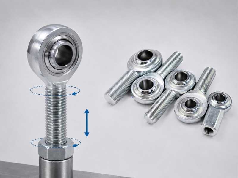
Table of Contents
A linkage that needs to be adjusted without disconnecting either end requires one thing: a way to change the assembly length while both rod ends stay bolted in place. Opposite thread directions on each end of the rod solve this exactly. Rotate the center tube clockwise, and both rod ends draw inward simultaneously. Rotate it counter-clockwise, and both extend. The connection points never move.
This is the turnbuckle principle applied to rod end linkages. It is how toe is set on adjustable suspension links, how pinion angle is corrected on a four-link, and how structural tie rods are tensioned in cable bracing systems without removing hardware from the structure.
The Geometry Behind It
A right-hand thread advances into its mating bore when rotated clockwise. A left-hand thread advances when rotated counter-clockwise. On a tube with one rod end threaded in from each side, opposite thread directions mean that the same rotation direction causes both ends to travel inward at the same time, or both to travel outward. Neither end needs to rotate independently.
The pitch determines how much linear movement you get per revolution. An M12 x 1.75 thread gives 1.75 mm of travel per end per full tube rotation. Across both ends combined, that results in a 3.5 mm change in overall linkage length per revolution. For fine geometry adjustment, coarse-pitch threads give faster length change; fine-pitch threads give more control per degree of rotation. Most rod end shanks use standard coarse pitch, which is adequate for suspension geometry but can overshoot on very sensitive applications if the tube is rotated quickly.
How to Identify the Left-Hand End
Left-hand rod ends are often easy to miss because their overall shape looks the same as right-hand versions. The fastest way to identify them is by the thread helix: a left-hand thread slopes upward to the left, while a right-hand thread slopes upward to the right.
Most rod ends are supplied with right-hand threads by default. Left-hand versions are typically marked with an “L” or “LH,” and some manufacturers add an identification groove near the end of the shank. If the marking is not visible, always verify the thread direction against the assembly drawing before applying torque.
Thread Engagement at the Adjustment Extremes
The adjustment range of an opposite-thread linkage is not unlimited. Each rod end must maintain a minimum thread engagement depth inside the tube at all times. The engineering standard cited across rigging and structural applications is 1.5 times the nominal thread diameter: for an M16 rod end, minimum engagement is 24 mm. For a 5/8-inch UNF rod end, the minimum engagement is 15/16 inch (or approximately 0.94 inches).
The problem occurs at the limits of adjustment. If a fabricator sets the initial length near the maximum extension of both rod ends to span a larger-than-expected gap, the tube may look correctly assembled but both shanks have minimal thread engagement. Under load, a shank with insufficient engagement will strip the thread rather than hold. The failure is abrupt and total.
Before installing, check that both rod ends are threaded in to at least 1.5x diameter even at the longest required length. If the tube needs to be longer to achieve this, the tube is undersized for the application. Extending it is the correct fix; accepting inadequate engagement is not.
The Jam Nut Problem: Why Linkages Self-Adjust in Service
This is where most explanations of opposite threads stop, and where the real failure mode begins.
The jam nut seated against the face of each rod end housing locks the shank at a set thread depth. When the jam nut is correctly torqued, the shank cannot rotate relative to the tube, and the linkage stays at the set length. When the jam nut is under-torqued, or when it gradually backs off under vibration, the shank is free to rotate.
Under alternating torsional loads, a rod end shank that is free to rotate will follow the path of least resistance. In most suspension and actuator applications, load reversals apply brief torsional impulses to the shank through the ball and housing. Over hundreds or thousands of cycles, a loose shank walks along the thread. The linkage gets shorter or longer without any deliberate input. This is the “self-adjusting link” problem discussed in suspension forums, and the cause is almost always a jam nut that was not torqued to specification.
Correct jam nut torque for stainless rod ends is higher than many fabricators apply. For an M12 stainless shank, target torque is 60 to 70 N·m. For M16, 100 to 120 N·m. The stainless-on-stainless contact between the jam nut and tube face requires anti-seize compound to reach these torques without galling, and the nut must be re-checked after the first load cycle because initial seating often relaxes the clamp slightly.
For assemblies subject to continuous vibration, safety wire passed through the jam nut and tube is the belt-and-suspenders solution used in motorsport and marine rigging. The wire does not replace correct torque. It provides a physical backup that limits rotation if the nut relaxes.
When RH/RH Is Correct
Not every rod end linkage needs to be adjustable in service. On a suspension four-link where the geometry is set once and never changed, a bent link where tube rotation is physically impossible, or any assembly where the link length is fixed by design, two right-hand rod ends are a legitimate choice. RH/RH reduces cost, simplifies spare parts, and in one sense is more resistant to catastrophic separation because the opposing thread directions on a correctly installed RH/RH link mean it cannot unwind itself into complete disengagement, the more one end unthreads, the more the other end threads in.
The trade-off is that any length adjustment requires removing at least one end bolt, making the change with a tape measure rather than by feel, and reinstalling. For initial setup on a build that will not require re-adjustment, this is a minor inconvenience. For a linkage that needs to be fine-tuned for alignment with the vehicle on the ground, it is impractical.
Stainless-Specific Notes
machining suppliers, but they are not always in stock. When sourcing LH stainless rod ends, confirm availability in the required grade before finalizing the design. 316 LH shanks in metric sizes above M20 can have longer lead times than equivalent RH parts.
The galling risk described in stainless thread assemblies applies equally to LH threads. The prevention is identical: apply nickel-based anti-seize to the shank thread before installation, start the thread by hand for the first several turns, and confirm no cross-threading before applying final torque. LH threads are not more or less prone to galling than RH; the material pairing and lubrication determine the risk, not the thread direction.
For stainless steel rod ends used in food processing or marine environments where corrosion drives grade selection, confirm the grade on the LH end matches the RH end. Mixed-grade assemblies, where one end is 304 and the other is 316, are a common sourcing error in multi-supplier builds and can create a weak point in the corrosion resistance of the assembly at the lower-grade component.
Send Inquiry Now
Related Resource
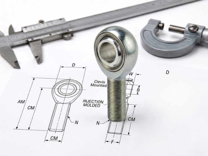
How Are Rod Ends Measured?
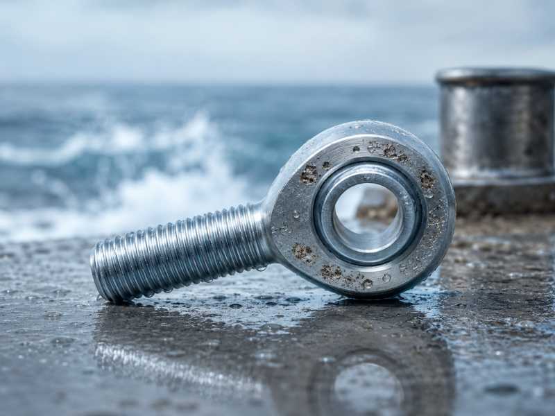
Pitting Corrosion in Marine Rod Ends
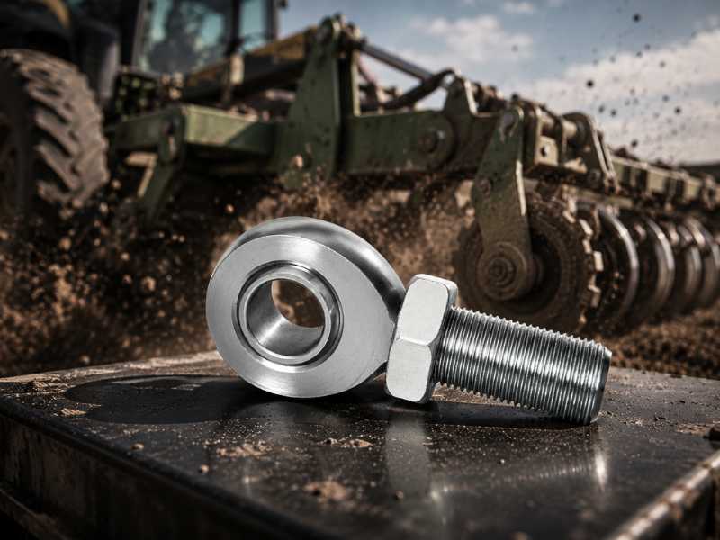
How Shock Loads Damage Rod Ends