- By Profab /
- April 3, 2026
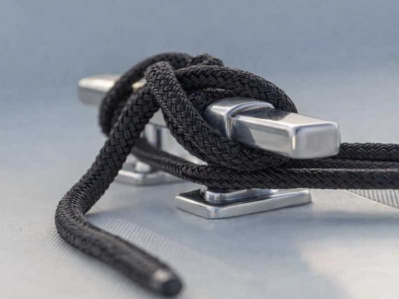
Table of Contents
A drifting boat rarely announces itself. The boat cleat holds through a full season, then fails. At 2 a.m. in a building swell, or in the moment a passing commercial vessel sends a wake through an otherwise quiet marina. Post-incident, the cause almost always traces back to hardware, not the knot: an undersized boat cleat, a cast fitting with internal porosity, a through-bolt seated in fiberglass without a backing plate. The hardware decision is made once and rarely revisited, which is exactly why it deserves more attention than it usually gets. This covers what boat cleats actually are, how the different types work, and what the material and mounting decisions mean for long-term service.
What a Boat Cleat Does, and How the Mechanics Work
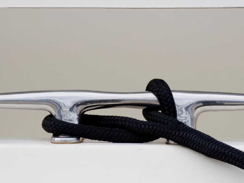
A boat cleat is a two-horned fitting that holds a dock line, mooring line, or anchor rode using a sequence of wraps and hitches rather than any locking mechanism. The design has remained standard marine hardware for centuries because it solves a real problem with minimal complexity: how do you hold a flexible rope under variable dynamic loads using a rigid fitting that attaches and releases quickly by a single person?
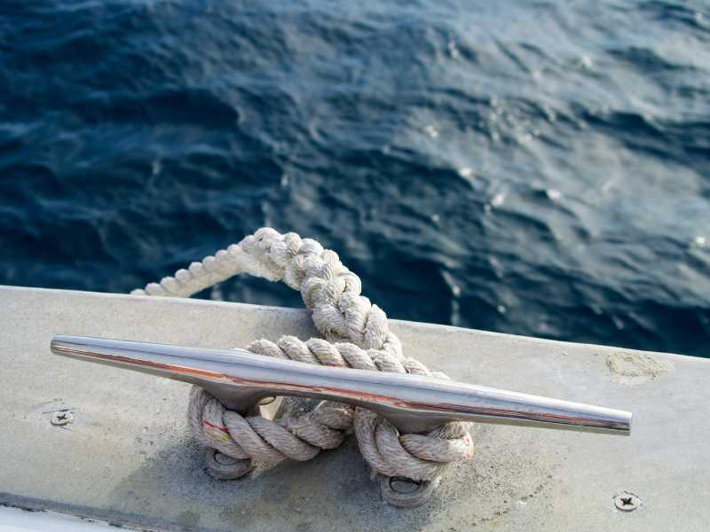
The answer is friction distribution. A correctly tied boat cleat hitch wraps the line around the body of the cleat first, creating a full-contact friction zone that carries the majority of peak load. The figure-eight over the horns adds directional resistance. The locking half hitch secures the tail. No cam mechanisms, no clamping force, no moving parts. Just geometry and friction against the cleat body. This simplicity is the design’s strength: there is nothing mechanical to fail beyond the structural integrity of the fitting itself and the quality of its mounting.
A standard horn cleat has three structural elements. The base is the flat mounting platform bolted to the deck or dock surface. Under surge or wind load, it transfers force to the fasteners and, through them, to the backing plate and structural substrate below. The body is the raised center section around which the initial round turn forms (this is where friction does most of its work, which is why the body profile and surface finish matter for line grip under load). The horns are the two projecting arms over which the figure-eight runs. Horn geometry, specifically projection length, angle, and tip profile, determines how cleanly the figure-eight seats and how reliably it releases without jamming after sustained load. Mounting holes or counterbored recesses at each end of the base accept the through-bolts; some boat cleats include a center groove or slot to facilitate line threading for quick-release applications.
Wikipedia entry on nautical cleats documents the historical range of configurations across vessel types. The horn cleat remains the dominant fitting for dock and mooring lines because no simpler design achieves the same combination of load capacity, reliable attachment, and quick release. These qualities matter more under adverse conditions than in calm ones.
Five Boat Cleat Types: What Each One Is Actually For
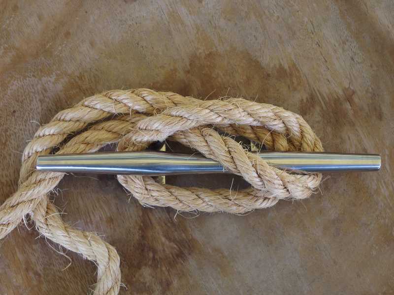
Horn cleats are the baseline. Two horns project horizontally from a raised body, accepting all standard cleat-hitch techniques and handling any load within the sizing specification. When a boat cleat is unspecified for dock line, mooring, or anchor rode use, this is the default. They work equally well on boat decks and fixed dock structures.
Pop-up and flush-mount cleats solve the deck-space problem. When stowed, they sit flush with the deck surface, eliminating the tripping hazard and clearing deck real estate. When deployed, they function identically to horn cleats: same geometry, same knot technique. This matters on performance craft, sailing yachts with frequent crew movement on deck, and commercial vessels where clear deck passage is a safety requirement. The spring mechanism adds mechanical complexity. Modern CNC-machined units in 316 stainless have demonstrated reliable field service life across commercial and recreational applications, but the mechanism requires periodic inspection and lubrication that a simple horn cleat does not.
Cam cleats use spring-loaded cams that grip a line fed through at the correct angle and release with a single upward pull. They do not accept cleat-hitch style knots and are not load-rated for dock line or mooring applications. Their application is running rigging on sailing vessels, sheet handling on racing craft, and situations where quick, one-handed release under tension is the requirement. Using a cam cleat as a mooring anchor is a misapplication; the load rating and release characteristics are not designed for sustained mooring loads and will fail without warning.
Clam cleats operate on ridged jaws rather than cams. Line is pressed between the jaws, which grip when tension is applied and release when the line is lifted clear. Common on racing dinghies, flag halyards, and light rigging where low-load, quick-release management is needed. Not for dock lines.
Dock cleats are heavy-duty horn cleats dimensioned for fixed dock installation rather than deck mounting. Commercial harbor installations typically run 12- to 16-inch units. Material ranges from galvanized steel in protected freshwater harbors to 316 stainless in tidal, coastal, and exposed locations.
| Cleat Type | Primary Use | Quick Release | Suitable for Dock Lines | Notes |
|---|---|---|---|---|
| Horn cleat | Dock lines, mooring, anchor rode | No | Yes | Standard baseline; most versatile |
| Pop-up / flush-mount | Deck-critical vessels | No | Yes (when deployed) | Requires periodic mechanism inspection |
| Cam cleat | Running rigging, sheets | Yes | No | Not rated for mooring loads; misuse fails silently |
| Clam cleat | Small craft, halyards | Yes | No | Light-load applications only |
| Dock cleat | Fixed dock mooring | No | Yes | Higher load ratings, larger sizes (12–16 in) |
The Material Decision: Why 316 Is the Minimum, Not the Premium
The grade question for boat cleats is not about premium versus budget. It’s about which alloys remain structurally intact in which environments after years of service. The failure modes of the wrong grade are not visible until the load event that exposes them.
Freshwater and sheltered harbors: 304 stainless (18% chromium, 8% nickel) and anodized aluminum both perform adequately. 304 forms a stable passive oxide layer in low-chloride environments, and regular rinsing with periodic passivation maintains its integrity without difficulty.
Coastal, tidal, and offshore environments: Seawater’s chloride concentration systematically attacks 304’s passive layer through pitting corrosion. Chloride ions penetrate the oxide layer at microscopic surface defects and initiate pits that deepen below the surface while appearing superficially stable from above. The structural consequence is what matters: pitting reduces load-bearing cross-section from the inside before visible surface degradation appears. Hardware can look acceptable and already be compromised at the through-bolt holes and horn root sections, which are the highest-stress locations on the fitting.
316 stainless addresses this by adding 2 to 3 percent molybdenum to the alloy composition. Molybdenum stabilizes the passive layer in chloride environments by raising the critical pitting potential, reducing the likelihood of pit initiation at the stress concentrations inherent in any structural fitting. ASTM A276 316 (the bar and shapes specification covering machined-from-solid product) is the minimum grade for tidal and coastal applications. Cast alternatives fall under ASTM A743 Grade CF8M; when comparing supplier quotes, confirm which standard applies, because this tells you the manufacturing method and grain structure behind the part.
316 versus 316L: The “L” means low carbon: a maximum of 0.03 percent versus 0.08 percent in standard 316. This distinction matters specifically for welded assemblies. Welding heats the surrounding metal through the sensitization temperature range, causing chromium carbide to precipitate at grain boundaries and depleting the chromium available for passivation in the heat-affected zone. 316L prevents this precipitation, maintaining corrosion resistance through the weld zone. For cleats machined from solid bar stock with no weld joints, 316 and 316L are equivalent in saltwater service. If the horns are welded to the base plate, specify 316L.
Cast versus machined: Investment cast cleats are formed by pouring molten alloy into a ceramic mold. The resulting grain structure can carry porosity, segregation, and surface-adjacent defects that post-processing may not fully address. CNC-machined cleats are cut from solid bar stock, producing a uniform grain structure without casting defects. The difference matters most at through-bolt holes and horn root cross-sections, which are the highest-stress points on the fitting under dynamic dock line load.
Passivation: Even 316 bar stock can pick up free iron contamination from CNC cutting tools during machining. Post-machining passivation treatment per ASTM A967 removes this surface contamination and optimizes the passive chromium oxide layer. For procurement teams, confirming that finished parts are passivated after machining is a meaningful quality checkpoint. It distinguishes machined parts that will perform as specified from those that look correct but carry latent surface chemistry issues.
Material selection by environment:
- Freshwater / sheltered harbor: 304 stainless or anodized aluminum is adequate
- Coastal and tidal: 316 stainless minimum (ASTM A276 for machined; ASTM A743 CF8M for cast)
- Offshore and exposed anchorages: 316 for machined components; 316L for any welded assemblies
- Fasteners: A4-70 or A4-80 (ISO 3506; equivalent to ASTM F593 Group 2 in North American specs). Do NOT use A2 (304-grade) bolts with 316 boat cleats; the mismatch causes rust streaks on deck that are incorrectly attributed to the cleat
- Post-machining passivation per ASTM A967: confirms passive layer integrity after CNC processing
Sizing and Installation: Two Places Where Spec-Correct Marine Cleats Still Fail
Sizing: The Line-Diameter Rule and Its Limits
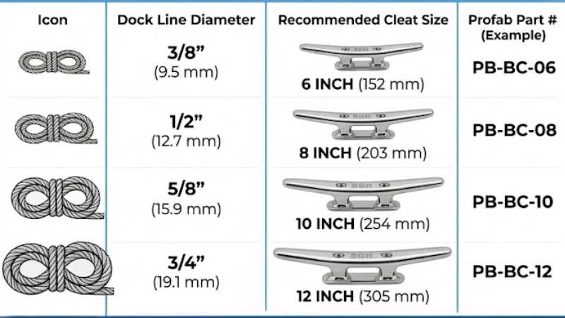
The standard marine industry rule of thumb relates cleat length to dock line diameter: one inch of cleat length for every 1/16 inch of rope diameter, rounded up to the next standard size. This sizing convention is used across the industry to facilitate compliance with the structural performance thresholds defined in ABYC H-40, though the rope-to-cleat ratio itself is a functional handling guideline rather than a direct specification within that standard. In practical terms: a vessel running 1/2-inch dock lines needs at least an 8-inch cleat; 5/8-inch lines need 10 inches; 3/4-inch lines need 12 inches.
Vessel length is a rough proxy for line selection, but displacement, freeboard, and local conditions determine actual cleat loads more accurately. A light-displacement 28-foot powerboat in a protected marina has fundamentally different boat cleat loads than a 28-foot heavy-displacement offshore sailboat in a tidal berth with 2-knot current.
Two sizing errors are common in practice. The first is selecting for typical conditions rather than worst-case: a boat cleat that holds reliably through a calm summer season will see different loads from a 35-knot squall or wake surge from a passing commercial vessel. Size for the worst anticipated condition, not the median. The second is over-sizing out of a “bigger is safer” assumption. An oversized boat cleat paired with undersized line places the rope wraps at the wrong geometry on the horns, so the round turn doesn’t properly grip the body and the figure-eight sits at a shallow angle relative to load. Proportionality between line diameter and cleat length matters as much as absolute size.
Installation: What Lies Below the Deck
GRP (fiberglass) and wood decks are not structural fastener substrates under sustained dynamic loading. A screw driven into fiberglass holds until cyclical load concentrates at the screw head and the laminate fails in bearing or shear, typically without warning and often with collateral damage to the surrounding deck structure. Through-bolts distribute load to a backing plate on the underside of the deck, transferring it to a larger bearing area and preventing point failure. For any boat cleat carrying dock line, mooring line, or anchor rode load, through-bolting is not optional.
Backing plates must distribute load across a minimum of 4 square inches per fastener. The plate must bear against a flat surface; irregular or curved deck geometry requires a backing block to create proper bearing contact before tightening. A marine cleat through-bolted into fiberglass without backing will pull through under hard surge loading, typically taking surrounding laminate with it.
When stainless steel boat cleats are mounted to aluminum hulls or deck structures (common on commercial workboats and some performance recreational craft), direct metal-to-metal contact creates a galvanic couple that will corrode the aluminum substrate over time. Interpose an isolation gasket or apply Tef-Gel between the boat cleat base and the aluminum surface, and use nylon isolation bushings on the through-bolt shafts to break the electrical path. This applies in freshwater as well as saltwater; galvanic corrosion requires only an electrolyte in contact with dissimilar metals, not specifically salt.
What to Confirm Before You Order
Procurement teams specifying boat cleats for OEM builds, vessel refit, or commercial dock installations need three things confirmed: material certification, manufacturing method, and post-processing treatment.
Material certification means a Material Test Report (MTR) confirming the heat number, chemical composition, and mechanical properties of the specific bar or billet stock used to make the part. Grade markings stamped on the fitting are not a substitute. They identify the intended specification, not the verified composition of the delivered part. For 316 or 316L in saltwater service, the MTR is the only reliable verification of molybdenum content. This matters particularly when sourcing from facilities where multiple alloys share production equipment.
Manufacturing method (machined from solid bar versus investment cast) determines the grain structure and defect exposure described above. For high-load and safety-critical applications, confirm machined from solid bar stock before approving the order. CNC-machined parts will reference ASTM A276; cast parts will reference ASTM A743 CF8M.
Post-machining passivation per ASTM A967 confirms that surface-contaminating free iron has been removed and the passive layer optimized after CNC processing. Suppliers who passivate as standard practice will document it; those who don’t are unlikely to mention it unless asked.
For procurement teams and OEM builders sourcing precision-machined marine fittings with full documentation, Profab Machine manufactures boat cleats stainless in 304 and 316 alloys, CNC-machined from solid bar stock at its Ningbo facility, passivated to ASTM A967, with MTR documentation and dimensional traceability on request.
The Short Version
Boat cleats are simple hardware with consequential failure modes. Specify 316 for any saltwater or tidal application; 316L if the assembly is welded. Use A4-70 or A4-80 fasteners (not A2) and confirm grade with an MTR rather than a surface marking. Size to dock line diameter using the 1-inch-per-1/16-inch convention, accounting for worst-case conditions. Through-bolt with backing plates. Isolate dissimilar metals on aluminum hulls. Ask specifically for machined-from-solid and post-machining passivation when the application demands it. The hardware decision is made once; the consequences of the wrong one arrive at the worst possible time.
Send Inquiry Now
Related Resource
How to Stop Your Boat Cleats from Squeaking
How to Size Your Boat Cleats Correctly
Backing Plates Decide Whether Your Boat Cleat Actually Holds