
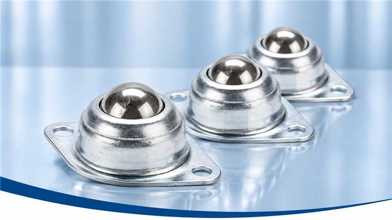
For a flat, even bottom, space ball transfer units no wider than the smallest edge of the load divided by 2.5, and size each unit for one third of the load weight. The first rule keeps the load from tipping into the gap between units. The second covers the fact that, because of unevenness and dimensional tolerances, only about three units carry the weight at any moment. The table below gives the short version.
| Input | Rule | Example: 40 kg crate, 400 x 600 mm |
|---|---|---|
| Maximum spacing | Smallest edge of the load ÷ 2.5, for a flat, even bottom | 400 ÷ 2.5 = 160 mm |
| Stricter spacing (one maker) | Smallest edge ÷ 3.5 | 400 ÷ 3.5 = about 114 mm |
| Load per unit | Load weight ÷ 3 | 40 ÷ 3 = about 13.3 kg |
| Units under the load | At least 3 at any position; count them on your layout | At least 6 on a 160 mm square grid |
| Uneven bottom | Reduce the spacing further | Check against the maker's data |
How Far Apart Should Ball Transfer Units Be?
Three maker technical documents give the same spacing rule for a load with a flat, even bottom: divide the smallest edge of the load by 2.5. One of them describes the limit as the spacing at which the load "reliably remains on the ball transfer units and cannot tip into the intervening spaces". A wider spacing lets a corner or an edge of the load drop between two balls.
A fourth maker uses a more cautious figure. It divides the shortest dimension by 3.5, so that at least three units touch the article along its shortest side at any time. The two rules are not contradictory, since both aim at stable support, but they give different pitches. When you have the data sheet for the series you will fit, use the figure in it. When you do not, use the smaller of the two spacings.
Why the smallest edge sets the spacing
The short side sets the limit, because the load has the least overlap with the balls there. A 400 x 600 mm crate has a 400 mm short side, so the short side controls. Measure the footprint that actually touches the balls, not the outer size of the load. A pallet with open feet, a tray with a rim, or a crate with a recessed base has a smaller contact edge than its overall size suggests.
Sizing the Load Per Unit
The required capacity of each unit is one third of the load weight. The reason given in the maker documents is practical: a load generally rests on only three units at a time, because of unevenness and dimensional tolerances. When one ball sits a little lower, the others carry the weight. Two makers add that the count of load-bearing units may be used when the ball height tolerance is good, and one says the factor of 3 can be increased for higher positioning accuracy. One third is therefore the safe default and not a law of nature.
Two conditions come with the rule. One maker states that its capacity values apply only to units installed upright. Another says its ratings apply in any mounting position, so read the data sheet for your series. The typical catalog values in the size table on the Profab ball transfer units page also show a lower ball-down figure, about half the ball-up figure or less.
Worked example: a 40 kg crate
Take a 40 kg crate with a 400 x 600 mm flat base on a square grid of units.
- Spacing: 400 ÷ 2.5 = 160 mm is the maximum spacing under the 2.5 rule of three makers. On a 160 mm grid a 400 mm edge can have only two rows. For at least three across the short edge, use the stricter 3.5 rule, 400 ÷ 3.5 = about 114 mm.
- Units under the crate: on the 160 mm grid, a 400 mm edge spans two or three rows and a 600 mm edge spans three or four columns, so at least six units are under the crate. On the 114 mm grid at least 15 are.
- Load per unit: 40 kg ÷ 3 = about 13.3 kg, even though six or more units share the load when everything is level.
- Size: the typical catalog ball-up values in the size table on the Profab page (not Profab ratings) are about 12 kg for a 15.8 mm (5/8 in) ball and about 25 kg for a 19 mm (3/4 in) ball. The 15.8 mm value is under 13.3 kg, so the 19 mm ball is the first size above the figure.
The table figures are typical values from published catalogs, rounded and for reference only. Confirm the rating for the actual unit before ordering.
How Many Units Go Under a Load
On a square grid with spacing s, a load of length L and width W always touches at least floor(L/s) x floor(W/s) units, and at most (floor(L/s)+1) x (floor(W/s)+1). For the 400 x 600 mm crate on a 160 mm grid that is 2 x 3 = 6 at least and 3 x 4 = 12 at most. On a 114 mm grid it is 3 x 5 = 15 at least and 4 x 6 = 24 at most.
A pallet touches the balls through its runners or deck boards, so count with that footprint and not the outer size. A heavier load shows why the size check matters: a 500 kg load gives about 167 kg per unit, which points to a heavy-duty unit and a check of the ball size and the housing. Data sheets often give loads in newtons, and 40 kg is about 392 N (kg x 9.81). If one table carries loads of several sizes, apply the spacing rule to the smallest edge of the smallest load.
Layout: Square Grid or Staggered Rows
A square grid is the simplest layout and suits a load that moves in two directions at right angles. A staggered or triangular pattern changes where the load contacts the balls for each direction of travel. One maker's technical sheet notes that a conveyor has many more movement directions at crossings and branches than on straight runs. It adds that the best arrangement depends on the direction of travel.
A second maker works two examples for a 375 x 375 mm item of 3,500 N. A centrally placed center of gravity is held by five units in a triangular pattern. An off-centre one is held by eight units in a right-angled triangle. Both obey the 375 ÷ 2.5 = 150 mm limit, and both size each unit for one third of the load (1,166.7 N). The example uses more units for the off-centre case.
Center of gravity
If the load is heavier at one end, check the layout with the weight where it really sits. The units nearest the heavy end carry more than the average. Put an extra row there, or choose a larger ball size for that corner.
Uneven Bottoms and Shock Loads
One maker's technical sheet says that for an uneven load it may be necessary to reduce the spacing even further. A bottom that is warped, ribbed, flexible or made of loose boards touches fewer balls at any moment, so each one carries more than one third. A flexible bag or a sagging tray can also dip between units even at the standard spacing.
Spring-loaded ball transfer units suit positioning and buffering stations. The built-in spring absorbs shock and returns the ball to its full height. Stroke, spring force and mounting direction depend on the series, so take them from the data sheet and do not assume a rating from the type name.
Shock is a separate question from spacing. A load dropped onto the balls from height, or a heavy item landing hard on a few units, may exceed the one third figure. Treat drop loads as their own check, and use a heavy-duty or spring-loaded unit in the landing area.
Ball Height, Mounting and Speed
In practice, ball heights should match across the group, because a unit that stands high takes more than its share and one that stands low carries little. Mount the units on a flat plate or machined seats, and check the ball heights with a straightedge before the first load.
Speed also matters. The maker figure for the maximum conveying speed is 2 m/s, and with larger units frictional heat can already raise the temperature at 1 m/s, depending on the load. The friction value is roughly 0.005 at 1 m/s, but it varies with use. These numbers belong to one maker's range, so check the speed limit of the series you choose.
Symptoms That Mean the Layout Is Wrong
| What you see | Likely cause | What to change |
|---|---|---|
| The load tips or catches between two balls | Spacing too wide for the smallest edge | Add units or move to a closer grid |
| One ball shows flats or a crushed seat | Load per unit above the rating, or one unit standing high | Recheck the one-third figure and the ball heights |
| The load rocks as it moves | Ball heights differ, or the plate is not flat | Shim or machine the seats and compare heights |
| Marks on the underside of the load | Soft or finished bottom surface under ball contact | Check the surface hardness against the ball, as one maker advises, and the load per unit |
| Balls stiffen after washdown | Dirt or product in the housing | See the ball transfer unit problems guide |
What to Send for a Ball Transfer Unit Quote
Send the details below to Profab Machine. We make stainless steel ball transfer units to your drawing or sample in 304, 316L and 17-4PH, in flange, stud and recessed mounting. Our engineers check the ball size, mounting and load before production.
- Load weight and the footprint that touches the balls (smallest edge and the other dimension)
- Condition of the load bottom: flat and rigid, ribbed, flexible or uneven
- Direction of movement and any turning or branching points
- Mounting space: plate thickness, hole size or flange pattern, and height limit
- Washdown, chemicals or salt, so we can match the grade
- Impact or drop loads, if any
Conclusion
Take the spacing from the smallest edge of the load, divide by 2.5 or use the maker's own figure, and size each unit for one third of the weight. Tighten both for an uneven bottom, and keep drop loads as a separate check. If you need units made to a layout, send the list above to Profab Machine and we will confirm the ball size, mounting and grade before we quote.