
Most ball joint selection mistakes happen when someone skips the environment question and goes straight to size. Thread size M8, bore 8mm, done. The joint arrives, it fits, and six months later it’s seized because the material was wrong for where it was installed.
The selection process has a sequence. Work through it in this order and you’ll arrive at the right specification without having to go back to the beginning.
Step 1: Define the Environment First
The environment determines what material you need, and the material affects load ratings, cost, and availability. Get this wrong and the rest of the selection doesn’t matter.
Dry, indoor, non-corrosive. Standard carbon steel or chrome steel ball joints are appropriate. No special material requirements. Zinc plating is adequate for light surface protection.
Outdoor exposure, humidity, moderate contamination. Zinc plating fails quickly in sustained outdoor conditions. This is the minimum threshold where stainless steel starts making sense economically. Not because carbon steel can’t handle occasional moisture, but because the maintenance interval to keep it functional becomes shorter than most applications justify.
Salt water, coastal environments, marine. This is where the material decision is non-negotiable. Carbon steel corrodes at the bearing interface within one season of salt spray exposure. Standard stainless (304) is significantly better but still susceptible to chloride-induced pitting over time. 316L, with its molybdenum content, is the correct baseline for any application that sees sustained chloride exposure.
Chemical washdown, CIP cleaning, food processing. CIP cleaning cycles use alkaline solutions (typically NaOH at 0.5–2% concentration at 60–80°C), then acid rinses, then water. Carbon steel and zinc-plated hardware degrades rapidly in this chemistry. 316L stainless is the standard for food-contact and pharmaceutical equipment.
Extreme loads, motorsport, high-cycle fatigue. If the driving constraint is load capacity rather than corrosion, the material choice shifts. Chrome steel (GCr15/52100) offers higher hardness and load ratings than stainless at equivalent size. This is the ball material in most precision rod ends and high-performance joints.
Step 2: Understand the Load Type
Ball joints carry load in different ways depending on the application, and not all joints handle all load directions equally well.
Radial load acts perpendicular to the joint’s axis, which is the primary design load for most linkage ball joints. A ball joint in a conveyor diverter, an actuator end fitting, or a gate linkage is carrying radial load.
Axial load acts along the joint’s axis. Most ball joints carry some axial load, but their axial capacity is typically lower than radial capacity. If your application has significant axial forces, verify the axial load rating specifically, not just the general load rating.
Dynamic vs. static load. A joint that holds a fixed position under load has different requirements from one that cycles continuously. Dynamic applications generate fatigue stress that accumulates over time. The relevant rating for a cycling application is the dynamic load rating, not the static one. Using a static load rating to size a joint in a continuous-motion application will give you a part that appears correctly sized but wears out early.
Shock loading. Impact loads can be several times the nominal load and act on the joint for very short durations. A joint sized to its nominal load capacity with no margin will be at risk from shock loads in equipment that starts and stops under load, encounters debris, or operates in terrain with unpredictable inputs. A safety factor of 2 to 3 on top of the nominal dynamic load is common practice for shock-prone applications.
Stainless steel ball joints carry 75 to 80% of equivalent chrome steel load ratings at the same bore size. If you’re replacing a chrome steel joint with stainless, verify you have sufficient load margin at that reduced capacity before finalizing the specification.
Step 3: Determine the Angular Range You Need
Ball joints allow angular movement between the connected components. The angular range varies by design, and using a joint near or at its angular limit causes edge loading that accelerates wear.
Standard ball joints in the DIN 71802 range typically allow 15 to 18 degrees of angular deflection. This is adequate for most pneumatic cylinder end fittings, valve linkages, and actuator connections where the misalignment between components is modest.
High misalignment designs extend this to 25 to 30 degrees. These are needed when:
- The joint connects components that move through a large arc during operation
- Suspension or linkage geometry changes significantly through the range of motion
- The installation has inherent misalignment that a standard joint would bind against
If you’re designing a new linkage, minimize the operating angle and use a standard joint. If you’re retrofitting into an existing geometry that demands large angular movement, check the rated angle before assuming any ball joint will work.
Step 4: Sort Out Thread Configuration and Size
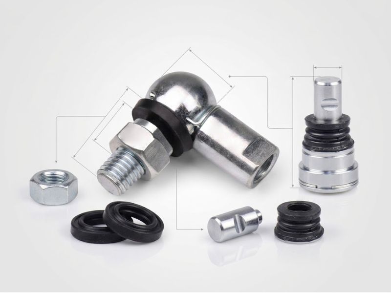
Ball joints are available in male thread (external shank), female thread (internal bore), and combinations. The thread configuration must match what the joint connects to.
Male thread is more common for end fittings on rods, cylinder stems, and adjustable linkages. The shank threads directly into or onto the mating component. Jam nut locks the position.
Female thread accepts a stud, bolt, or threaded rod. Common where the ball joint mounts onto a fixed stud, or where the application requires the ball joint body to be the connecting element rather than the shank.
Thread standard matters for interchangeability. Metric threads (M6 through M24 covers most applications) and UNF inch threads are the two main families. DIN 71802 is the dimensional standard for many industrial ball joints. Confirm the standard before ordering. A metric M8 and a 5/16-24 UNF are close in size but not interchangeable.
Left-hand thread versions are available for applications where a right-hand thread would unscrew under operational torque, or where a paired left/right thread arrangement is needed for length adjustment without disassembly.
Step 5: Choose the Material
This is where the environmental decision from Step 1 converts into a specific material specification.
Carbon steel (with zinc or phosphate coating): Lowest cost. Highest load capacity per unit size. Correct for dry indoor applications with no corrosion exposure. Wrong for anything wet, chemical, or outdoor long-term.
Chrome steel (GCr15 / 52100): The standard for precision rod ends and high-performance ball joints. Harder than stainless (typically HRC 58–64 vs HRC 18–22 for austenitic stainless in the annealed condition). Higher load ratings, better wear resistance at the contact surface. Not corrosion resistant. Used in motorsport, aerospace, and precision linkages where load capacity is the primary driver and the environment is controlled.
Stainless steel (304/316L): The correct material where corrosion resistance is the design constraint. 304 for general outdoor and light chemical exposure. 316L where chloride or CIP chemistry is present. Load capacity is 75 to 80% of chrome steel at equivalent size. This is a real trade-off that must be accounted for when sizing. See the previous post on what stainless steel ball joints are used for for detailed environmental selection guidance by grade.
Engineering plastics (igus, PEEK, POM): Self-lubricating, light weight, non-conductive, and fully corrosion resistant. Load capacity is significantly lower than steel, typically suitable for light-duty automation, sensor positioning, and laboratory equipment. Not appropriate for structural loads or dynamic high-force applications. Temperature range is limited compared to steel. The right choice when weight, lubrication-free operation, or electrical isolation matters more than load capacity.
Chromoly steel (4130/4140): Used in motorsport and custom fabrication where high strength and weldability are needed. Not corrosion resistant without coating. Common in heim joint and rod end builds for suspension and steering on dedicated off-road or race vehicles.
Step 6: Sealed or Open, PTFE or Metal-to-Metal
The bearing contact surface inside the ball joint determines maintenance requirements and performance in contaminated environments.
Metal-to-metal contact with grease fitting (greasable): Highest load capacity. Requires periodic relubrication. Suited for heavy-duty applications where maintenance access is available and loads exceed what PTFE liners can handle. Grease also flushes contamination out of the joint when you service it, which is an advantage in dirty environments.
PTFE-lined (self-lubricating): No grease required. Lower friction. Better suited for food-contact and pharmaceutical applications where lubricant cannot be used. Lower dynamic load rating than metal-to-metal at equivalent size. PTFE liners can be degraded by sustained exposure to hot alkaline CIP solutions above approximately 80°C. Check operating conditions against liner specifications.
Sealed (with integral lip seals): Retains lubricant and excludes contamination passively. Better for daily-driven or infrequently maintained applications. The seal limits maximum angular articulation slightly compared to an open joint. Seal material must be compatible with the chemical environment. NBR for general use, FKM (Viton) for CIP and chemical process environments.
Conclusion
If you’re in a hurry: define your environment first, then look up the load rating for your load case, then confirm the angular range covers your geometry, then match the thread. The material follows from the environment. The liner follows from the maintenance situation. If you get the environment right, the rest of the selection is mostly dimensional.
Profab Machine manufactures stainless steel ball joints in 304, 316L, and 17-4PH in DIN 71802 and custom configurations, with material certifications for food, offshore, and pharmaceutical applications.