- By Profab /
- April 20, 2026
Table of Contents
A ball joint fails before its design life for one of two reasons: the environment was more aggressive than expected, or the load was higher than specified. The first failure mode gets plenty of attention in material selection discussions. The second gets less, and it tends to surface in the worst possible way, through a premature failure in service that traces back to a spec sheet misread at the sourcing stage.
Load ratings on stainless steel ball joints are not intuitive. The numbers look straightforward until you realize that static and dynamic ratings measure different things, that axial and radial capacities are often separated by an order of magnitude, and that stainless steel carries a structural load penalty compared to carbon or chrome steel equivalents. Most of these points appear nowhere in the product listing. They live in the engineering footnotes.
What follows works through each factor that shapes real-world ball joint capacity, so engineers and procurement teams can choose a joint that actually survives its application.
Static vs Dynamic: Two Numbers, Two Different Questions
Every ball joint spec sheet lists at least two load figures. Understanding what each one answers is the starting point for correct selection.
The static load rating answers: how much load can this joint sustain without causing permanent deformation that would affect its function? More precisely, it defines the load at which the contact stress between the ball and race produces a specific, controlled level of permanent deformation, typically 0.0001 times the ball diameter per ISO and DIN conventions. This is not a fracture limit. It’s a deformation limit calibrated to preserve dimensional integrity. For a joint in a static structural application, the static rating is the primary specification.
The dynamic load rating answers a different question: under oscillating or rotating load, what force can this joint carry across its rated service life, defined as the load at which 90% of an identical production batch will reach or exceed their nominal life expectancy? Dynamic capacity is always lower than static capacity for the same joint. In applications with repeated articulation, the dynamic rating governs.
A third figure sometimes appears: ultimate load, typically defined as 1.5 times the static limit load (using the aerospace convention of limit load as the maximum expected service load and ultimate load as the fracture boundary at 1.5x). This is the load at which the joint body may deform plastically but will not fracture. It defines the outer boundary of the joint’s structural survival, not its operating range. Using ultimate load as a design point is a red flag.
For practical sizing, the rule is straightforward: structural joints under sustained or rarely-varying load use the static rating as the primary criterion. Articulating joints under cyclic loading use the dynamic rating. When both conditions apply, both ratings must be checked independently.
Three load ratings and what they mean:
- Static limit load: Maximum load before permanent deformation that impairs function. Primary criterion for non-articulating joints.
- Dynamic load rating: Load at which 90% of joints reach rated service life under oscillation. Primary criterion for articulating joints.
- Ultimate load: Fracture prevention limit, typically 1.5× static limit. Not a design point. A failure boundary.
The Stainless Steel Load Penalty
This is the figure that catches buyers off-guard most often: stainless steel ball joints carry load ratings approximately 75 to 80 percent of their carbon or chrome steel equivalents at the same dimensional specification.
The reason is material hardness. Standard chrome steel ball joints use 52100 alloy steel for the ball, hardened to around HRC 60-64. This high surface hardness enables the joint to support high contact stresses at the ball-race interface without plastic deformation. Stainless steel ball joints typically use 440C martensitic stainless steel for the ball, which achieves HRC 58-60 after hardening, close to but measurably below 52100’s capability. The race materials in stainless joints are also typically lower hardness than chrome steel equivalents, compounding the gap.
In practical terms: if a chrome steel rod end with a 10mm bore has a static radial load rating of, say, 10 kN, the equivalent stainless steel version at the same bore is likely rated around 7.5 to 8 kN. The dimensional footprint is identical. The capacity is not.
This matters most when teams source stainless steel versions as direct replacements for chrome steel ball joints without adjusting the load calculation. In a non-corrosive application, the swap is straightforward. In a corrosive application where you’ve already bumped up to the next size to gain headroom, inadvertently switching to stainless may reduce your actual load margin by 20 to 25 percent below what the previous calculation assumed.
The mitigation is simple: when substituting stainless for carbon or chrome steel, verify load ratings from the stainless steel-specific data sheet, not from the equivalent carbon steel reference.
Axial vs Radial: The Ratio That Surprises Most Engineers
For linear bearings and rolling element bearings, axial and radial load capacities are often in the same order of magnitude. Spherical plain bearings and ball joints behave very differently.
In a typical stainless steel ball joint, the axial load capacity is often only 5 to 10 percent of the radial load capacity. A joint rated for 8 kN radially may accept only 400 to 800 N in the axial direction. This is a function of geometry: the ball-race contact area that resists radial loading is much larger than the area resisting axial thrust. The ball is designed to articulate, not to carry pulling force along its bore axis.
The consequence is significant in any application where the load direction is not purely perpendicular to the joint bore, or where the structural configuration creates both radial and axial components simultaneously. Linkage systems, actuator rod ends, and steering hardware often experience combined loading. If only the radial rating was checked during selection, the axial component may be driving the joint into failure long before the rated radial capacity is reached.
Calculating combined loading for spherical plain bearings follows established methods. The most direct approach is to verify that both the radial and axial components independently fall within their respective rated limits. For combined loading under ISO 12240, a simplified equivalent radial load formula applies when both components are present simultaneously. Consult the manufacturer’s specific calculation guidance, as the formula varies by joint design.
| Bore Size (M thread) | Radial Working Load Range (typical SS) | Axial Working Load Range (typical SS) | Max Misalignment (standard) | Best For |
|---|---|---|---|---|
| M6 | ~1.5 kN | ~0.1–0.15 kN | 8–12° | Light instrumentation, control linkages |
| M10 | ~5–8 kN | ~0.4–0.8 kN | 8–12° | General industrial, food processing |
| M16 | ~18–24 kN | ~1.5–2.4 kN | 6–10° | Structural linkages, marine hardware |
| M24 | ~50–70 kN | ~4–7 kN | 6–8° | Heavy machinery, offshore equipment |
Note: Values are representative working load ranges for 316/440C stainless ball joints to DIN ISO 12240-4. Working loads are conservative estimates accounting for dynamic service conditions. Always verify against the supplier’s certified data sheet for the specific grade and design.
Misalignment and Its Effect on Load Capacity
Stainless ball joints are selected in part because they accommodate angular misalignment, which is often the entire point of using a ball joint over a rigid connection. But misalignment has a cost: it reduces the effective load capacity of the joint.
The physics is straightforward. When a ball joint operates at its maximum rated misalignment angle, the elliptical contact area between ball and race shifts toward one edge of the race. The load distribution across that contact becomes progressively less uniform, concentrating stress at the edge of the contact zone. As misalignment angle increases toward its rated maximum, this edge loading reduces the maximum allowable load before the limit deformation criterion is reached.
Standard stainless ball joints conforming to spherical plain bearing standards typically carry a maximum misalignment rating in the range of 6 to 12 degrees, depending on bore size. Smaller bore joints generally allow higher angular misalignment relative to their diameter; larger bore joints are more constrained. High-misalignment variants exist for applications requiring 20 degrees or more, but these designs trade load capacity for angular range.
In practice, the critical sizing error is specifying a joint at both its maximum load and its maximum misalignment simultaneously. At full rated misalignment, effective load capacity may be reduced by 15 to 30 percent from the nominal rating. If your application runs at or near the maximum angle in the spec, factor in a corresponding reduction when checking load margins.
The factor of safety conventions for ball joint applications reflect this compounding uncertainty. Normal loading with predictable direction: a factor of 1.0 to 1.5 on rated capacity is acceptable. Applications with shock loads, vibration, or combined radial-axial loading: 1.5 to 2.0 or higher. When misalignment, combined loading, and stainless steel’s load penalty are all in play simultaneously, a factor of 2.0 or above is the conservative and defensible choice.
Four factors that reduce effective ball joint load capacity below the catalog number:
- Stainless steel vs chrome steel construction: multiply rated capacity by 0.75–0.80
- Axial load component: verify separately; axial capacity is typically 5–10% of radial
- Operating near maximum misalignment angle: allow for 15–30% capacity reduction
- Shock or cyclic loading: apply safety factor of 1.5–2.0 to calculated load
Applying all four corrections simultaneously is the difference between a joint that lasts and one that doesn’t.
Getting the Size Right from the Start
The goal of load rating analysis is to arrive at a joint specification where the worst-case actual load, with all correction factors applied, sits comfortably below the rated capacity. “Comfortably” means different things in different applications, but a working rule is to target no more than 60 to 70 percent of rated static capacity under normal operating load in corrosive environments, where inspection intervals may be longer and failure consequences higher.
A practical sizing sequence for stainless steel ball joints:
- Identify the maximum load in service, separating radial and axial components.
- Identify the operating misalignment angle and compare against the joint’s rated maximum.
- If misalignment is above 50 percent of the rated maximum angle, apply a 15 to 30 percent derating to the static radial rating.
- Select a joint where the derated radial capacity exceeds the maximum radial load by the appropriate safety factor (1.5 minimum for dynamic applications, 2.0 for shock or combined loading).
- Verify separately that the axial component is within the joint’s axial rating, even if it appears small relative to the radial load.
- Confirm load ratings from the stainless steel-specific data sheet. Do not use carbon or chrome steel ratings as a proxy.
Profab Machine manufactures precision stainless steel ball joints in 316, 316L, and 2205 duplex, machined to DIN ISO 12240-4 and custom drawings with full dimensional traceability. For applications where load margins and grade selection both matter, our stainless steel ball joint range covers standard and custom bore sizes with documented load ratings.
Send Inquiry Now
Related Resource

Maintenance Secrets for Stainless Steel Ball Joints
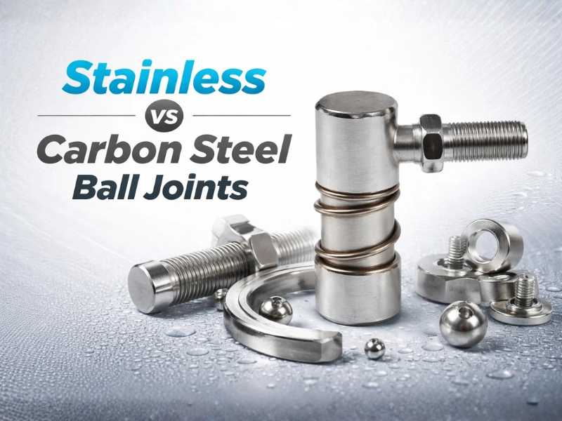
Stainless vs Carbon Steel Ball Joints
How to Read Load Ratings for Stainless Steel Ball Joints