5 Hidden Shadow Areas That Spray Balls Often Miss
- By Ray Wang /
- July 3, 2026
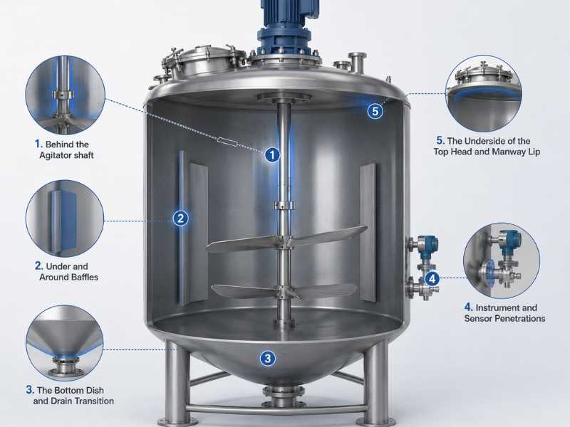
Table of Contents
A spray ball can be perfectly sized for your tank, running at the right pressure, with the correct nozzle pattern for your residue type, and still leave residue behind. Coverage on paper and coverage in practice are different things in any spray ball cleaning setup. The gap between them is almost always the same five locations, and they show up in tank after tank regardless of industry.
Here’s where to look, and why each one defeats a properly specified spray ball.
1. Behind the Agitator Shaft
The agitator shaft is the single most common shadow source in any tank with mixing capability. A stainless steel spray ball mounted at the top of the tank sprays in a pattern designed around an empty vessel. The shaft running through the center of that pattern blocks a portion of every spray cone that would otherwise reach the far wall.
The shadow isn’t a single dot. It’s a vertical band running the full height of the tank, directly behind the shaft from the spray ball’s point of view, widening slightly as you move further from the nozzle. In tanks with side-entry agitators, the shadow shifts depending on shaft angle and can shift again if the agitator is removable and reinstalled at a different orientation between cleaning cycles.
The fix is rarely a bigger or higher-pressure spray ball. A single top-mounted ball physically cannot reach around a shaft no matter how much pressure you push through it. The standard correction is a secondary spray device positioned to spray across the shadow band from a different angle, or a rotary spray ball whose spray pattern sweeps through multiple angles over a full rotation rather than holding a single static pattern.
2. Under and Around Baffles
Baffles are installed specifically to disrupt flow during mixing, which means they’re also specifically positioned to disrupt your spray pattern during cleaning. The underside of a horizontal baffle, and the wall area directly behind a vertical baffle relative to the spray ball, both sit outside direct line of sight from a top-mounted device.
This shadow is harder to diagnose than the agitator shaft shadow because baffles vary so much in geometry between tank designs. A full-height vertical baffle creates a continuous shadow strip. A series of smaller baffles staggered around the tank wall creates a pattern of smaller, scattered shadows that don’t look like a single obvious gap when you’re inspecting visually.
Mapping this shadow requires knowing the baffle geometry before you finalize spray ball placement, not after. If baffles weren’t part of the original spray coverage calculation, retrofitting coverage later usually means adding a side-mounted ball at the height where the baffle creates the worst blockage, angled to spray underneath rather than relying on the top-mounted unit to compensate.
3. The Bottom Dish and Drain Transition
The transition zone where a tank’s sloped or dished bottom meets the outlet or drain nozzle is consistently undercleaned, and it’s consistently the area swab tests flag. Spray from a top-mounted ball arrives at a shallow angle by the time it reaches the bottom of the tank. That shallow angle means low impingement force exactly where heavier residues settle under gravity.
This matters more than it looks like it should. Vessel cleaning with static spray balls relies primarily on chemical wetting and the cascade of a falling film rather than high direct impact. This means a shadow at the bottom dish represents a critical coverage failure: if the chemical solution does not wet the surface, cleaning stops entirely. No amount of detergent concentration or cycle time compensates if the spray pattern cannot reach the steel. A widely used industry rule of thumb calls for roughly 2.5 to 3 gallons per minute per foot of vessel circumference to guarantee full sidewall wetting. This target is independent of tank height but directly dictates whether the bottom transition receives a sufficient falling film to remove residue.
The drain nozzle itself adds a second problem. Any branch connection, including the drain, creates a stagnant zone if its length-to-diameter ratio exceeds what’s acceptable for the cleaning method. These are formally tracked as dead legs in pharmaceutical and biotech vessel design. The same geometry issue applies in food and beverage tanks even where the formal dead-leg calculation isn’t required. A drain nozzle with excessive unflushed length will not get cleaned by spray coverage alone regardless of how well the rest of the tank is covered.
4. Instrument and Sensor Penetrations
Temperature probes, level sensors, and sampling ports that penetrate the tank wall create small but persistent shadows directly behind their mounting point, plus a secondary shadow where the probe body itself blocks spray from reaching the wall surface immediately around the penetration.
These shadows are small in surface area compared to an agitator shaft shadow, which is exactly why they get missed during visual inspection and caught during microbial swab testing instead. A facility running consistent positive results at a specific sample point, cycle after cycle, while the rest of the tank passes clean, should treat sensor penetrations as the first suspect rather than assuming the spray ball itself has failed.
The probe geometry itself often makes this worse. A probe with a flat mounting flange or a sensor housing with sharp internal corners gives residue more surface area to adhere to inside a zone that’s already getting reduced spray contact. Where probe replacement isn’t practical, the correction is usually a spray ball reposition or the addition of a small auxiliary nozzle angled specifically at the penetration cluster rather than relying on the primary spray pattern to handle it.
5. The Underside of the Top Head and Manway Lip
The area immediately under the tank’s top head, particularly around the manway opening and any gasket lip, gets less attention than it should because it’s physically close to the spray ball and assumed to be well covered by default. In practice, a spray ball mounted on a stub pipe extending down from the top head sprays outward and downward. The zone directly above and around the spray ball’s own mounting point, including the underside of the manway flange, sits in the ball’s own shadow.
This is the shadow most likely to get caught only during a formal coverage verification, because it’s invisible during a normal walk-around inspection where you’re looking down into the tank rather than up at the underside of the closure. Riboflavin fluorescence testing is the standard verification method for this kind of check: a riboflavin solution is applied to the interior surface before a cleaning cycle, and any area the spray fails to reach shows up under UV light after the cycle completes, since riboflavin only washes off where the spray actually makes contact.
The fix is usually mechanical rather than chemical. Repositioning the spray ball lower on its mounting stub, or selecting a model with an upward-angled nozzle set specifically to cover the head underside, closes this gap without changing flow rate or pressure.
Running a Spray Ball Coverage Test to Confirm You've Closed the Gaps
Mapping shadow zones on paper is the starting point, not the finish line. A formal spray ball coverage test using the riboflavin fluorescence method described above is the standard validation approach for regulated industries. For less formal verification, a flour-and-water test, where a thin flour paste is applied to suspect zones before a cycle and visually checked afterward, catches the same gaps at a fraction of the cost, though it doesn’t generate the documentation a validated process requires.
Either method works only if you’ve correctly identified where to look first. The five zones above account for the overwhelming majority of shadow-related cleaning failures across tank designs, which makes them the right starting point before assuming a spray ball needs replacement or upgrading to a higher-pressure model that may not solve a geometry problem at all.
Profab Machine manufactures stainless steel spray balls in static and rotary configurations for food, beverage, and pharmaceutical tank cleaning applications. If your vessel geometry includes internal obstructions that complicate coverage, spray pattern and placement can be reviewed against your actual tank drawing.
Ray Wang is an engineer at Profab Machine with more than 20 years of experience in stainless steel applications and automotive parts. Over the years, he has built deep expertise in precision machining, material behavior, and practical engineering solutions. His hands-on background and strong focus on quality help ensure every project meets demanding performance and reliability standards.
Ray Wang is an engineer at our company with more than 20 years of experience in stainless steel applications and automotive parts. Over the years, he has built deep expertise in precision machining, material behavior, and practical engineering solutions. His hands-on background and strong focus on quality help ensure every project meets demanding performance and reliability standards.
Send Inquiry Now
Related Resource