- By Profab /
- May 20, 2026
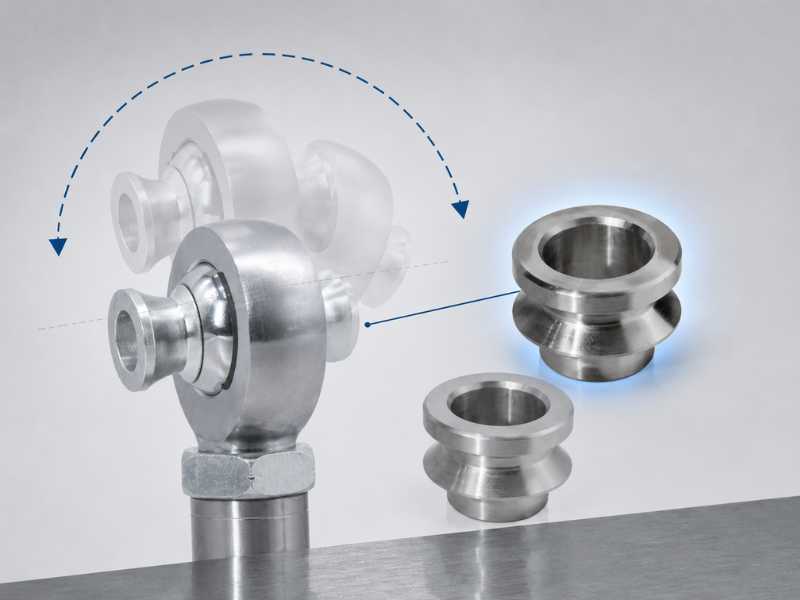
Table of Contents
A standard rod end has a hard angular limit. When the bolt or shank contacts the inner edge of the housing bore, the joint binds. In most catalog rod ends, that limit falls between 12 and 18 degrees depending on housing geometry and ball width. For many industrial and structural applications, that range is adequate. For high-travel suspension linkages, steering systems with compound geometry, and any assembly where the joint must accommodate large angular excursion without binding, it is not.
Misalignment spacers solve this by changing the geometry at the ball-to-housing interface. The mechanism is straightforward once you understand what causes the angular limit in the first place.
Why Standard Rod Ends Have an Angular Limit
A rod end ball sits inside a housing bore. The ball is spherical. The housing bore is cylindrical, with an inner race that contacts the ball across a defined surface band. When the joint pivots, the ball rotates inside the race. The limit occurs when the edge of the ball, or the bolt passing through the ball bore, contacts the rim of the housing.
Two dimensions determine where that limit falls: the ratio of ball diameter to housing bore diameter, and the width of the ball relative to the housing opening. A larger ball relative to the housing opening means the edge of the housing reaches the ball further from the equator, limiting pivot before contact. A narrower housing opening allows more travel before the shank contacts the rim.
Standard rod ends are not optimized for maximum angular travel. They balance load capacity, compact dimensions, and standard pin compatibility. The angular limit is a geometric consequence of those priorities, not a separate design choice.
How Misalignment Spacers Work
A misalignment spacer is a precision-machined collar, typically convex on its outer surface, that inserts into the bore of the rod end from each side. Installed in pairs, the two spacers sit flush against either face of the ball.
The convex outer profile of each spacer continues the spherical radius of the ball outward beyond the housing bore rim. From the housing’s perspective, it now sees a larger effective ball diameter at the opening. The edge of the housing contacts the curved spacer surface rather than the flat face of the ball, and that contact point is further around the sphere. The joint can pivot further before the spacer profile contacts the housing rim.
The result is angular travel in the range of 25 to 34 degrees, depending on spacer geometry and rod end housing dimensions. This is roughly double the travel of the unmodified joint.
The trade-off is bore diameter. The spacers occupy the ball bore, so their inner diameter, which becomes the pin or bolt hole for the assembly, is smaller than the original bore. A rod end with a 3/4-inch bore fitted with high misalignment spacers typically accepts a 5/8-inch bolt. This reduction must be verified against the shear load requirement for the specific application.
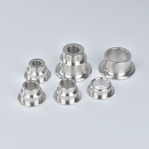
Three Spacer Types and When Each Applies
Standard misalignment spacers are flat-faced cylinders sized to fill the gap between a narrow ball and a wide bracket. They do not extend angular travel. Their purpose is to center the ball in the bracket opening and distribute load across the full ball width. Use these when the bracket slot is wider than the ball, and no additional travel is needed.
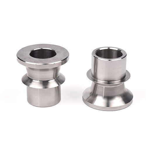
High misalignment spacers have the convex outer profile that extends the ball radius. These are the correct choice when angular travel beyond the standard rod end limit is required. They reduce the bolt bore as described above. Always used in pairs, one per side.
Cone spacers are a middle option. The tapered outer profile provides a modest improvement in angular travel, typically 3 to 6 degrees beyond standard, while allowing the original bolt size to be retained in some configurations. Useful when only marginal additional travel is needed and bolt size reduction is not acceptable.
Callout: Angular Travel Comparison
Standard rod end, no spacers: 12 to 18 degrees typical.
With cone spacers: 15 to 22 degrees typical.
With high misalignment spacers: 25 to 34 degrees typical.
High misalignment rod end (extended ball, integral): up to 34 degrees, full bore retained.
Angular travel figures vary by housing geometry. Confirm rated misalignment angle against the manufacturer’s specification for the specific rod end and spacer combination.
The Bolt Size Trade-Off in Practice
The bore reduction from high misalignment spacers is not a flaw in the design. It is a deliberate geometric consequence: the spacer wall thickness that creates the convex profile occupies radial space inside the bore. The question is whether the smaller bolt can handle the applied load.
Shear load capacity scales with bolt cross-sectional area. Moving from a 3/4-inch to a 5/8-inch bolt reduces the cross-sectional area by approximately 31 percent. In most suspension and linkage applications, the bolt is not the limiting element in the load path. The rod end ball and housing typically govern. But in high-load applications, particularly steering linkages under extreme off-camber loads or actuator assemblies with dynamic shock inputs, the reduced bolt size must be calculated against the expected shear load with an appropriate safety factor before the spacer configuration is finalized.
Using a grade 8 or equivalent high-tensile bolt with the reduced diameter partially offsets the cross-section reduction. A 5/8-inch grade 8 bolt has a higher shear capacity than a 5/8-inch grade 5 bolt at the same diameter, and may be adequate where the original 3/4-inch grade 5 or grade 8 bolt was over-specified.
Material Specification for Misalignment Spacers
Spacers are typically machined from 303 or 304 stainless steel. 303 is the standard for most catalog spacers because it machines cleanly to tight dimensional tolerances and the convex profile requires accurate surface geometry to function correctly. The sulfide inclusions that improve machinability in 303 reduce its corrosion resistance relative to 316 in chloride environments, so marine and coastal applications should specify 316 spacers, even if the catalog standard is 303.
Dimensional fit between the spacer outer diameter and the rod end bore is the critical tolerance. A loose fit allows the spacer to shift laterally under load, concentrating contact stress at one point on the housing rim rather than distributing it across the convex profile. Spacers should seat firmly in the bore with minimal radial clearance. Confirm dimensional compatibility between the spacer outer diameter and the rod end bore specification before ordering.
When to Use High Misalignment Spacers vs. a High Misalignment Rod End
High misalignment rod ends, where the ball itself has an extended or profiled diameter built in, achieve similar or greater angular travel without reducing the bore size. The ball geometry incorporates the misalignment function directly, so the original bolt diameter is retained. Load capacity is generally higher than a standard rod end with add-on spacers because the contact surface area between ball and race is not reduced by the spacer geometry.
The practical choice between the two comes down to what is already in the assembly.
If the rod end is a standard unit already installed or already specified, retrofitting high misalignment spacers is the lower-cost path to additional travel. No housing or rod end changes required.
If the application is being designed from scratch and maximum travel with full bolt size is the requirement, a high misalignment rod end is the cleaner specification. It eliminates the spacer as a separate component, reduces part count in the assembly, and avoids any concern about spacer fit or lateral shift.
For production OEM assemblies, specifying a high misalignment rod end with integral geometry is generally preferable to a standard rod end plus spacers for the same reason that integrated solutions are preferable to assembled work-arounds: fewer parts, fewer tolerance stack-up concerns, fewer failure modes.
Installation Notes
High misalignment spacers are directional. The convex face points outward toward the housing rim; the flat or recessed face seats against the ball. Installing them reversed eliminates the angular travel benefit entirely and can damage the housing bore under load. Confirm orientation before assembly.
Both spacers must be installed simultaneously from each side before the bolt is inserted. Inserting one spacer and attempting to load the bolt before the second spacer is seated will off-center the ball in the housing and prevent correct seating.
After assembly, verify that the joint moves through its full intended range without binding before the assembly goes under load. High misalignment spacers that are correctly installed and dimensionally matched should allow smooth travel to the rated angle. Any resistance short of the rated limit indicates a dimensional mismatch or incorrect orientation.
Profab Machine supplies high misalignment spacers and rod ends with full material certification from Ningbo, China.
Send Inquiry Now
Related Resource
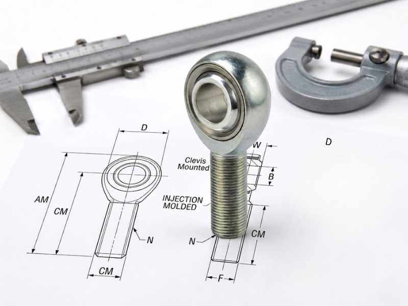
How Are Rod Ends Measured?

Pitting Corrosion in Marine Rod Ends
How Shock Loads Damage Rod Ends