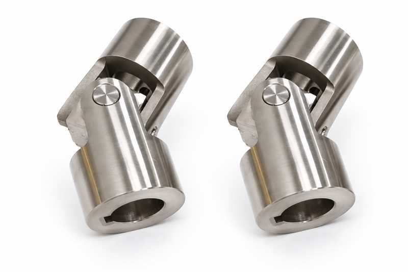
A universal joint vibrates at twice shaft speed for three main reasons: a large working angle, unequal end angles, or yokes on the middle shaft that are out of phase. Wear, imbalance and a flexible support cause the rest. A single joint at an angle never turns its output at a steady speed. The first job is to measure the angle and see whether a second joint cancels it.
| Working angle | Output speed range, single joint | Swing as % of input speed |
|---|---|---|
| 5° | 0.996 to 1.004 times input | 0.8% |
| 10° | 0.985 to 1.015 times input | 3.1% |
| 15° | 0.966 to 1.035 times input | 6.9% |
| 20° | 0.940 to 1.064 times input | 12.4% |
| 30° | 0.866 to 1.155 times input | 28.9% |
The values are calculated from the standard single-joint speed formula, explained in the next section. They describe the geometry of a cross-type joint, not the rating of any Profab part.
Why a Single Joint Cannot Run Smoothly at an Angle
In a cross-type joint, the output speed follows a published kinematic formula: output speed equals input speed times cos β, divided by (1 − sin²β · cos²θ). Here β is the working angle and θ is the input shaft position. At β = 0 the ratio is exactly 1. At any other angle it swings between cos β and 1/cos β.
The cos²θ term repeats every half turn, so the output speeds up and slows down twice per revolution. The kinematic disturbance therefore sits at two times shaft speed, not one. At 1,200 rpm the shaft turns at 20 Hz and the joint disturbs the drive at 40 Hz.
A published patent on driveline vibration states that the torsional vibration of a joint is proportional to the square of its operating angle. Doubling the angle from 5° to 10° does not double the swing, it quadruples it, which matches the table above (0.8% against 3.1%).
What the swing looks like in rpm
Take a shaft turning at 1,200 rpm through a single joint at 10°. The output runs between 1,182 and 1,219 rpm, a swing of about 37 rpm, twice every turn. A driven machine with high inertia, such as a heavy roller or a long screw, feels that swing as torque ripple. A light one feels it as noise.
Our own product data says the same thing in simpler terms: above 15°, vibration and bearing wear rise in precision drives, so choose a double joint when the output must stay steady. The stainless steel universal joints page lists the angle limits for each type.
Equal Angles: The First Thing to Measure
Two joints in series, with a short shaft between them, can cancel each other's swing. The cancellation needs the working angle at the input joint to equal the working angle at the output joint. The same patent describes the equal and opposite angles case, where the swing from the first joint is substantially cancelled by the equal and opposite swing from the second.
When the angles differ, the cancellation is partial. For small angles in one plane, the leftover behaves like a single joint at an angle of about √(β₁² − β₂²). That follows from the square law above. It is a field estimate, not a rating.
A worked example: an input joint at 10° and an output joint at 6° leave a residual of √(100 − 36) = 8°. The shaft vibrates as if one joint were running at 8°, which is far from the zero you wanted. Setting the second angle to 10° removes it.
How to measure the working angle
The working angle is the angle between the axes of the two shafts a joint connects, not the total deflection of either shaft. Measure it at both ends of the shaft with an inclinometer or a protractor held on the shaft axes. Repeat at the extremes of any suspension or machine travel, because an angle that is equal at rest can become unequal when the machine moves.
Phasing: Which Way the Yokes Should Face
Phasing is the angular relationship between the two yokes on the shaft between the joints. When the cross-bore axes of those two yokes are parallel, the patent calls it a zero phase angle. With zero phase and equal angles, the output turns at the same steady speed as the input.
Turn one yoke 90° and the cancellation is lost. For small angles the two swings now add instead of subtract, so the output swings by roughly twice as much as one joint alone would produce. At 1,200 rpm and 10° each, that is about 73 rpm peak to peak against 37 rpm for a single joint. A shaft rebuilt after a repair, with a yoke assembled out of position, shows exactly this symptom.
One caution applies. Some sources quote 90° instead of zero because they measure the phase angle from a different reference, so the numbers differ even when the physical alignment is the same. Follow the drawing or the marks stamped on the shaft before you rotate anything.
Supports and Resonance: Why One Frame Shakes
The same joint can run quietly in one frame and shake in another. A joint at an angle applies oscillating moments to the shafts it connects, bending them perpendicular to the plane of the shafts and loading the bearings that carry them. That is why a drive that shakes only under load often points at the angle and the supports, not at a worn joint.
If the frequency of that disturbance, two times shaft speed, falls near a natural frequency of a shaft, a bracket or the machine frame, the amplitude jumps. A symptom that appears in one speed band and fades on either side can point to resonance. The fix is to change the speed band, stiffen the support or reduce the angle, which cuts the swing by the square law.
Check the support bearings and mounts before you change the joint. A loose pillow block or a cracked bracket makes any joint angle look worse than it is.
Telling Joint Geometry From Wear and Imbalance
Several different faults produce shaking in a shaft with joints, and each leaves a different fingerprint. Frequency is the quickest separator. A phone with a vibration app or a handheld analyser shows whether the main peak sits at one times or two times shaft speed.
| What you see | Likely cause | What to check |
|---|---|---|
| Peak at 2× shaft speed, present with new joints | Working angle too large, or two angles unequal | Measure both angles at rest and at travel limits; use the residual estimate |
| Peak at 2× that began after a rebuild | Yokes out of phase | Compare the marks or arrows; check that the cross-bore axes on the middle shaft are parallel |
| Shaking mostly under load, fading when unloaded | Often moments from a large angle acting on weak supports | Support bearings, mounts, and the angle itself |
| Peak at 1× shaft speed, rising with speed | Imbalance, bent shaft or yoke runout | Dial indicator on the shaft and yoke faces; balance check |
| Clunk when torque reverses, play at the cross | Worn bearings or cross | Hand test, then replace the joint |
| Stiff or rough spot once per turn | Seized or corroded cross, dry spline | Turn the shaft by hand with the drive disconnected |
The second row is easy to miss. A shaft that has been stripped and rebuilt can be fully serviceable and still wrong, because a yoke can be refitted out of position. The bad universal joint symptoms guide covers the wear stages for the rows about play and noise.
A Five-Step Check Before You Replace Anything
- Disconnect the drive and turn the shaft by hand. Any stiff spot or play at the cross means a worn or seized joint, and you can stop here.
- Find the frequency. One times shaft speed points at imbalance or runout. Two times points at angle, phasing or the supports, though a worn cross can add one-times and higher orders.
- Measure both working angles at rest and at the travel limits, and compare them.
- Check the yoke marks on the middle shaft, or confirm that the cross-bore axes are parallel if the drawing calls for zero phase.
- Inspect the supports. Loose bearings, cracked brackets and soft mounts turn a small disturbance into a large one.
If every step passes and the shaking persists, the angle is probably more than a single joint can tolerate for that machine. A double joint with equal angles, or a different drive layout, largely removes the swing instead of reducing it.
When the Angle Cannot Be Reduced: Layout Options
Sometimes the machines cannot move, and the angle is what it is. The choice then comes down to how much swing the driven machine can take. Our selection table gives the starting point for each range of working angle.
| Working angle | Layout | Note |
|---|---|---|
| 0° to 5° | Single joint, needle or pin-and-block | Swing is under 1%; suits alignment correction and long life |
| 5° to 15° | Single joint, needle bearing | Standard continuous drive; swing reaches about 7% at 15° |
| 15° to 30° | Single joint, or a double joint where output speed must stay steady | Double joint needs equal angles at both yokes |
| 30° to 45° | Single joint, pin-and-block only | Low speed, and torque derated to about half |
| Over 45° | Double joint, or a custom layout | Low-speed or manual operation only |
A double joint is longer than a single one, so check the axial space first. A telescopic joint adds a splined section that lets the shaft change length while it turns, so its spline fit and stroke are specified separately from the angle.
These figures come from our product range. Speed and torque limits fall as the angle rises, so confirm both at your actual working angle before you order.
What to Send for a Joint Selection
If the check shows the joint is the wrong one for the job, send the details below to Profab Machine. We make single, double and telescopic joints in 304, 316L and 17-4PH, bored and keyed to your drawing or sample.
- The working angle at each end, and whether both lie in one plane
- Shaft speed in rpm and the torque to be transmitted
- Shaft diameters, keyways and the length available between the machines
- Wet, washdown or salt-air exposure, so we can match the grade
Conclusion
Measure the two working angles first, keep them equal, and confirm that the middle yokes are in phase before you suspect wear. Two times shaft speed points at geometry, one times at imbalance. If you need a new joint or a double joint to fit the angles you measured, send the list above to Profab Machine and we will confirm the angle, torque and bore before production.